More likely a product of its time and limited experience. There probably were no discrete power transistors of >200kHz ft yet. We'll never kill the low open-loop BW thing, it just won't die.
Well, people keep preferring CFA. and this open-loop thing is one difference that may correlate? Maybe SR. What else is there to correlate with such popular findings? Isnt distortion in typical sense of harmonics produced.
Anyone care to venture out and suggest a reason for this CFA preference?
THx-RNMarsh
Last edited:
Anyone care to venture out and suggest a reason for this CFA preference?
Until it's determined that there actually is a preference the question is moot. Sorry no metadata.
BTW one can design a VFA that equals any CFA slew rate and getting low open-loop BW is trivial just cripple the VAS and lest I forget VFA's with ppm distortion at full power have been presented here. No cheating either an H-bridge input is a VFA not a CFA period there is no argument possible.
Last edited:
Until it's determined that there actually is a preference the question is moot. Sorry no metadata.
BTW one can design a VFA that equals any CFA slew rate and getting low open-loop BW is trivial just cripple the VAS and lest I forget VFA's with ppm distortion at full power have been presented here. No cheating either an H-bridge input is a VFA not a CFA period there is no argument possible.
There actually is a preference. so not moot.
I am aware of the adapted VFA etal for similar CFA performance. and I said the distortion wouldnt be a reason for preferring CFA or their VFA equals (CFA with high Z buffer port).
Perhaps the new fast VFA sound same as CFA. But wide OL BW is there in both.
Anyone else have idea why CFA and fast VFA are prefered?
THx-RNMarsh
So yes, Chris, I will just have to live with the discontinuity.
If you implement your attenuate-while-switching mechanism using FETs, there is a possibility of ramping the gate up slowly (~ 1 second rise time ??), flipping the polarity relay, and then ramping the gate down slowly (~ 1 second fall time ??)
This way you get a "pause" rather than a discontinuous "click".
Me, I'd pick the MOS type of FET rather than the junction type, but it's undeniably true that lots and lots of gear uses JFETs for analog switching, quite successfully.
Well, people keep preferring CFA. and this open-loop thing is one difference that may correlate? Maybe SR. What else is there to correlate with such popular findings? Isnt distortion in typical sense of harmonics produced.
Anyone care to venture out and suggest a reason for this CFA preference?
THx-RNMarsh
Oh my, let's not talk about presumption. Who are these people you refer to? If you want to take it as YOU, then by all means take the claim but don't generalize. I could care less the topology -- now your stats are all broken.

Please go try to pick a fight elsewhere. This is so hashed over and useless even by terms of this thread.
Oh my, let's not talk about presumption. Who are these people you refer to? If you want to take it as YOU, then by all means take the claim but don't generalize. I could care less the topology -- now your stats are all broken.
Please go try to pick a fight elsewhere. This is so hashed over and useless even by terms of this thread.
I havent generalised at all. Last year or more I brought this up and detailed the manufacturers who follow what i said here now. Just updated with LC CFA added to the list. Without going back there and starting over, it seems no one has a clue as to why and so you dont either. Fine. Next?
It seemed that maybe...maybe... what was brought up in JC's art he put up might be related in some way.
Anyone else care to give a try at an answer?
THx-RNMarsh
Last edited:
Is there an industry standard to insure consistent phasing throughout the initial recording, mixing, production process?
The AES has a standard. But even if used throughout system, many old microphones are still used for various reasons and they are not consistent with newer AES standard. You can rewire all the microphones to be all consistent but I doubt any studio has done that.
You could use power mosfet(s) to do your polarity reversal. Use type with very low On resistance.
THx-RNMarsh
Last edited:
so these reliably hearing CFA 'magic' could've made an easy US$10k ? Richard Clark Amplifier Challenge FAQ - seems like no one has yet

But wide OL BW is there in both.
No you're probably referring to gain BW product not the same thing. You can make virtually any amplifier have a 100Hz or so OL BW it makes no difference to anything. This discussion is very tired.
Dear mr. WurcerYou can make virtually any amplifier have a 100Hz or so OL BW it makes no difference to anything.
I am surprised by this sentence.
If such an amplifier, once closed, has a flat response curve (as we expect) up to, says 200KHz, what about his distortion curve VF frequency ?
Just to understand your position, it looks you were working for A.D./PMI. They were the manufacturers of integrated circuits the most implied in current-feedback ones. I wonder why you seems, now, downgrade this topology.
Yours sincerely,
Tryphon Tournesol.
Last edited:
Dear mr. Wurcer
I am surprised by this sentence.
Ifsuch an amplifier has a flat response curve (as we expect) up to, says 200KHz, what about his distorion curve VF frequency ?
Absolutely no problem. And do not take into account just only dominant pole frequency compensation (-20dB/decade behind OL corner), you may get 60-80 dB loopgain (feedback factor) at 20kHz and still keep your amp well stable.
VAS loading and flattening OL frequency response has the only effect - higher distortion. Though we speak now about inaudible distortion levels.
I wonder why you seems, now, downgrade this topology.
I don't, I only promote a real understanding of what is going on in the face of all this historical baggage much of which could very well be left in the bin. The audio community works in its own little ivory tower sometimes ignoring the rest of the engineering world.
Dear mr. Wurcer
I am surprised by this sentence.
If such an amplifier, once closed, has a flat response curve (as we expect) up to, says 200KHz, what about his distortion curve VF frequency ?
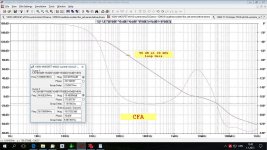
If Pavel's explanation doesn't make sense, try to think of two integrators:
1.) 10 Hz knee with 100 dB gain
2.) 100 Hz knee with 80 dB gain
Over the grand majority of audio bandwidth, how different are these two? (and then appreciate you'll be wrapping this gain as feedback for a closed-loop gain of, say, 20 dB.
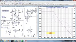
Absolutely no problem. And do not take into account just only dominant pole frequency compensation (-20dB/decade behind OL corner), you may get 60-80 dB loopgain (feedback factor) at 20kHz and still keep your amp well stable.
VAS loading and flattening OL frequency response has the only effect - higher distortion. Though we speak now about inaudible distortion levels.
In both amp types is possible to get 80 dB or more loopgain at 20 kHz with special type of compensation.
Closed loop gain in both cases is 28 dB.
Attachments
Last edited:
Did-you mean that a power amp with an OLB flat to 2KHz (IE constant feedback amount in all this bandwidth) will mesure and sound the same that an amp with a corner at 10Hz ?Over the grand majority of audio bandwidth, how different are these two?
When I say "mesure", i'm talking about every aspects: Damping factor, distortion curve VS frequency, slew rate, noise, settling time.
Yours sincerely,
Tryphon Tournesol
Last edited:
Did-you mean that a power amp with an OLB flat to 2KHz (IE constant feedback amount in all this bandwidth) will mesure and sound the same that an amp with a corner at 10Hz ?
When I say "mesure", i'm talking about every aspects: Damping factor, distortion curve VS frequency, slew rate, noise, settling time.
Yours sincerely,
Tryphon Tournesol
Hi Tryphon,
I want to start from the beginning rather than jumping into all these extra features. But I'd argue that if you took the two examples I gave you (assuming they're identical otherwise), you'd see extremely small differences. Extremely, as their loop gain above 100 Hz would be identical.
Now if we permute through a bunch of different 1 MHz GBW amplifiers (not unusual for an audio amplifier), you're going to see far more variation based on the actual design of the amplifier (just go look at the number of 10 MHz GBW, 100'ish dB DC gain opamps out there of all different performance).
Mathematically, you want to distribute as much of the feedback in the biggest loop you can make, but reality strikes when you get down to it (see: degenerating the differential pair). One can build that as a low, but higher open-loop bandwidth, or as a gigantic DC gain integrator, but, generally speaking, the latter fits that mathematical model. (Of course, there's examples lid Dadod's amp, too)
Proof's in the pudding!
- Status
- Not open for further replies.
- Home
- Member Areas
- The Lounge
- John Curl's Blowtorch preamplifier part II