OK, guys.
But no one really got what I find really interesting, namely the inability for any S/D DAC to present a 22.05 (44.1fs) signal that is only a couple of LSB's of amplitude. That is, as long as the oversampling rate is less than the number of bits. In this case some 2^18 times.
I can't understand what you really mean. I guess you mean 6bits quantizer SDM with 64OSR has only 6bits additional extension for its bit resolution. The total 12bits resolution is not adequate for 24bits resolution like pcm1704.If so, this is not the correct meaning of OSR.
Here is my SIM by Excel.I usually use Excel because the spreadsheet is basically the recursive formula which has the real number.The process of DSM or FIR can be seen step by step.It's easy for me to understand. DSM is also easy to visualize by Excel.
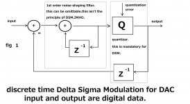
fig.1 is the simple 1st order DSM to be SIMed.The quantizer is 5bits.1 bit is also possible.But a little bit difficult to understand visually.Almost every circuit consists of input, output, and error.The output can be defined like this.
output=input +error
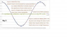
Regardless of quantizer resolution and OSR, this formula is true.fig.2 is input, output, and error SIMed by Excel. The output of SDM is usually difficult to understand without math.Even using math, it's not friendly.A rough estimation of the output spectrum is not easy. But the difference between output and input, which means error, is friendly for me. It apparently has much high-frequency noise and less low frequency.
And I'm sure the toggle frequency of error depends on OSR.The higher OSR is, the higher it toggles.In other words, high OSR can shift quantization noise far away.Large quantization bits decrease the amplitude of error on the other hand. Both decreases THD of error.It means the decrease of output THD.The true meaning of OSR and quantization bits can be guessed by fig.2 without math.
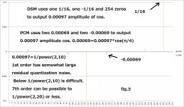
fig.2 is the SIM of large amplitude, 0.9*cos. Smaller amplitude is also possible to SIM.fig.3 is 0.00097 (1/power(2,10)). DSM also can output somewhat accurate data. But the residual quantization noise is large because of the 1st order.
If you use 7th order, as low as -120dBFS(1/power(2,20)) is possible as long as I measured the output of a real FPGA.
PCM and DSM are the way of digital recording.PCM is high resolution with low sample rate (a little bit higher than Nyquist).DSM is low resolution with high sample rate.Both solutions are possible.DSM is practically good at high accuracy.I can't say the sonic issue. It's the subjective issue.
Attachments
OK. I think it's time for me to give up, I just cant be convincing enough. But I must test that code, Marcel.
But I will give it one more try.
Take a pure 1 bit S/D device running at 128fs.
The weakest signal it can represent is just to let one of these 128 timeslices be 1 and the rest zero. If doing so, the weakest signal at maximum frequency ( fs/2 ) will be 1/128 of maximum amplitude.
Isn't this a striking picture? Disregarding any math. It's kind of a matter of common sense.
OK, Marcel, I will test your code and come back with some results, eventually.
you really have to get Higher Order Modulators, "Noise Shaping"
Delta Sigma simulation appears to be quite the thing in open source - python-deltasigma
Svitjod, your 1 lsb pulse for the entire base sample rate window is mistaken, way "too simple" for Higher Order Modulators
D-S makes new decisions on output bit pattern at each of the OSR time steps - the output is very 'busy', spans multiple bits of the 6 bit DAC
and relies on high order Analog filters to remove the Shaped Noise from the multibit DAC output
Last edited:
Please allow me ...OK. I think it's time for me to give up, I just cant be convincing enough. But I must test that code, Marcel.
But I will give it one more try.
Take a pure 1 bit S/D device running at 128fs.
The weakest signal it can represent is just to let one of these 128 timeslices be 1 and the rest zero. If doing so, the weakest signal at maximum frequency ( fs/2 ) will be 1/128 of maximum amplitude.
Isn't this a striking picture? Disregarding any math. It's kind of a matter of common sense.
OK, Marcel, I will test your code and come back with some results, eventually.
In essence, what you've described is a very basic "oversampling" process:
- begin with a *low-precision* quantizer, operating at some oversampling ratio (128Fs, for example)
- input this oversampled *low-precision* signal into a simple averaging (FIR) filter, with equally-weighted taps, and with a length equal to the oversampling ratio (128 taps) ... so you are only using 128 *low-precision* input signals, for example, to calculate each "high-precision* output.
And you've discovered a "resolution limit" to this very basic process

But what you're missing, are two VERY important aspects of more modern, more sophisticated oversampled quantizers :
1. Higher-order (more "aggressive") noise shaping (in addition to basic oversampling)
2. Higher-precision outputs are created with filters (FIR or IIR, analog or digital, it matters not for this discussion) that "remember" many, MANY more low-precision input samples than, simply, the oversampling ratio
Higher-order noise shapers, and the FIR or IIR filters that follow them, are virtually impossible to understand, completely, in the time domain. The frequency domain is where you need to look. Both domains contain the very same information, of course, but often one domain is easier to understand than the other ...
Last edited:
I've combined a few of my Pascal programs into one: it is now a complete interpolation-sigma-delta-decimation chain, albeit with somewhat primitive filters: simple linear interpolation and sixth-order CIC for decimation. For comparison I've added a second path with the same signal transfer function as the path with the sigma-delta, but without any quantization.
program sigmadelta_pbm_cic;
(* Sigma-delta modulator with embedded pulse width modulator-like *)
(* thing with randomly rotated pattern. *)
(* Combined with very simple interpolation and decimation: *)
(* linear interpolation and sixth-order CIC decimation filter. *)
(* For comparison, also includes a linear time-variant filter *)
(* with equal signal transfer, but no quantization or PWM. *)
uses Crt;
const
lengte = 25600;
PBMlengte = 8;
CICorde = 6;
oversampling = 256;
(* maxn is the largest absolute value that the CIC registers can contain, *)
(* it must be greater than the maximal CIC filter output signal before *)
(* the correction for CIC filter gain, that is, greater than the maximal *)
(* absolute value of state variable Mies[CICorde]. *)
maxn: int64 = round(exp(ln(oversampling)*CICorde)) + 1;
(* Coefficients for procedures sigmadelta and stf, made global so *)
(* consistency between the coefficients of these procedures is ensured. *)
c1 = 0.004766840354*PBMlengte/2;
c2 = 0.052844429735*PBMlengte/2;
c3 = 0.256703167298*PBMlengte/2;
c4 = 0.746792470683*PBMlengte/2;
c5 = 1.255604698776*PBMlengte/2;
i1 = 1;
i2 = 1;
i3 = 1;
i4 = 1;
i5 = 1;
d1 = 0.0005;
d2 = 0.004938272;
pi = 4*arctan(1);
type
signal = array[0..lengte] of extended;
integersignal = array[0..lengte] of integer;
CICstate = array[1..CICorde] of extended;
var
xin: extended;
xin_old: extended;
xin_new: extended;
filteredxin: extended;
filteredsdout: extended;
(* int1 to int5: integrator states of sigmadelta, rotatie: variable *)
(* of its rotating algorithm, kwant: latest quantizer value. *)
int1: signal;
int2: signal;
int3: signal;
int4: signal;
int5: signal;
rotatie: integer;
vastgelopen: longint; // tracks the number of quantizer clipping events
kwant: integer;
(* intnq1 to intnq5: integrator states of procedure stf, the linear *)
(* time-variant filter that matches the sigma-delta modulator's *)
(* signal transfer function. *)
intnq1: signal;
intnq2: signal;
intnq3: signal;
intnq4: signal;
intnq5: signal;
nokwant: extended;
sdout: integersignal; // output signal sigma-delta
stffilt: signal; // output signal stf
teller: longint; // counter
(* State variables of the CIC filters: *)
aap: CICstate;
noot: CICstate;
Mies: CICstate;
Wim: CICstate;
Zus: CICstate;
Jet: CICstate;
f: TextFile;
fsd: TextFile;
fdecim: TextFile;
procedure sigmadelta(xin: extended; var uit: integersignal; teller: integer; var int1: signal;
var int2: signal; var int3: signal; var int4: signal; var int5: signal; var rotatie: integer;
var kwant: integer; var vastgelopen: longint);
var
hulp: integer;
begin
if teller mod PBMlengte = 1 then
begin
kwant:=round(int5[teller-1]+Random+Random-1+PBMlengte/2);
(* Quantizer with triangular PDF dither. *)
if kwant<0 then
begin
kwant:=0;
vastgelopen:=vastgelopen+1;
end;
if kwant>PBMlengte then
begin
kwant:=PBMlengte;
vastgelopen:=vastgelopen+1;
end;
rotatie:=random(PBMlengte);
(*random integer from 0 up to and including PBMlengte - 1 *)
end;
hulp:=(teller-1+rotatie) mod PBMlengte;
if hulp<kwant then
uit[teller]:=1
else
uit[teller]:=-1;
int1[teller]:=(xin-c1*uit[teller]-d1*int2[teller-1]+i1*int1[teller-1])/PBMlengte+((PBMlengte-1)/PBMlengte)*int1[teller-1];
int2[teller]:=(int1[teller-1]-c2*uit[teller]+i2*int2[teller-1])/PBMlengte+((PBMlengte-1)/PBMlengte)*int2[teller-1];
int3[teller]:=(int2[teller-1]-c3*uit[teller]-d2*int4[teller-1]+i3*int3[teller-1])/PBMlengte+((PBMlengte-1)/PBMlengte)*int3[teller-1];
int4[teller]:=(int3[teller-1]-c4*uit[teller]+i4*int4[teller-1])/PBMlengte+((PBMlengte-1)/PBMlengte)*int4[teller-1];
int5[teller]:=(int4[teller-1]-c5*uit[teller]+i5*int5[teller-1])/PBMlengte+((PBMlengte-1)/PBMlengte)*int5[teller-1];
end; // procedure sigmadelta
procedure stf(xin: extended; var uit: signal; teller: integer; var int1: signal; var int2: signal;
var int3: signal; var int4: signal; var int5: signal; var nokwant: extended);
begin
if teller mod PBMlengte = 1 then
begin
nokwant:=int5[teller-1];
end;
uit[teller]:=2*nokwant/PBMlengte;
int1[teller]:=(xin-c1*uit[teller]-d1*int2[teller-1]+i1*int1[teller-1])/PBMlengte+((PBMlengte-1)/PBMlengte)*int1[teller-1];
int2[teller]:=(int1[teller-1]-c2*uit[teller]+i2*int2[teller-1])/PBMlengte+((PBMlengte-1)/PBMlengte)*int2[teller-1];
int3[teller]:=(int2[teller-1]-c3*uit[teller]-d2*int4[teller-1]+i3*int3[teller-1])/PBMlengte+((PBMlengte-1)/PBMlengte)*int3[teller-1];
int4[teller]:=(int3[teller-1]-c4*uit[teller]+i4*int4[teller-1])/PBMlengte+((PBMlengte-1)/PBMlengte)*int4[teller-1];
int5[teller]:=(int4[teller-1]-c5*uit[teller]+i5*int5[teller-1])/PBMlengte+((PBMlengte-1)/PBMlengte)*int5[teller-1];
end; // procedure stf
procedure CICfilter(inp: extended; var out: extended; var aap: CICstate; var noot: CICstate; var Mies: CICstate; CICorde: integer; maxn: int64;
teller: longint; oversampling: integer);
var
localcounter: integer;
begin
(* CIC decimating filter *)
aap[1]:=inp+aap[1];
if aap[1]>maxn then aap[1]:=aap[1]-2*maxn; // Folding applied to keep the state variables from exploding,
if aap[1]<-maxn then aap[1]:=aap[1]+2*maxn; // does not cause distortion as long as maxn > maximum output signal
for localcounter:=2 to CICorde do
begin
aap[localcounter]:=aap[localcounter]+aap[localcounter-1];
if aap[localcounter]>maxn then aap[localcounter]:=aap[localcounter]-2*maxn;
if aap[localcounter]<-maxn then aap[localcounter]:=aap[localcounter]+2*maxn;
end;
if teller mod oversampling = 0 then
begin
Mies[1]:=aap[CICorde]-noot[1];
if Mies[1]>maxn then Mies[1]:=Mies[1]-2*maxn;
if Mies[1]<-maxn then Mies[1]:=Mies[1]+2*maxn;
for localcounter:=2 to CICorde do
begin
Mies[localcounter]:=Mies[localcounter-1]-noot[localcounter];
if Mies[localcounter]>maxn then Mies[localcounter]:=Mies[localcounter]-2*maxn;
if Mies[localcounter]<-maxn then Mies[localcounter]:=Mies[localcounter]+2*maxn;
end;
noot[1]:=aap[CICorde];
for localcounter:=2 to CICorde do noot[localcounter]:=Mies[localcounter-1];
out:=Mies[CICorde]/exp(ln(oversampling)*CICorde);
end;
end; // procedure CICfilter
begin // main program
assign(f, 'PCMin.txt');
(* 100 kHz sample rate input signal *)
assign(fsd, 'SDMout.txt');
(* 25.6 MHz sample rate output *)
assign(fdecim, 'decimout.txt');
(* 100 kHz decimated output *)
reset(f);
Rewrite(fsd);
Rewrite(fdecim);
int1[0]:=0.0006779986543;
int2[0]:=0;
int3[0]:=0;
int4[0]:=0;
int5[0]:=0.00014553722;
intnq1[0]:=0;
intnq2[0]:=0;
intnq3[0]:=0;
intnq4[0]:=0;
intnq5[0]:=0;
sdout[0]:=0;
for teller:=1 to CICorde do
begin
aap[teller]:=0;
noot[teller]:=0;
Mies[teller]:=0;
Wim[teller]:=0;
Zus[teller]:=0;
Jet[teller]:=0;
end;
vastgelopen:=0;
kwant:=round(PBMlengte/2);
xin_new:=0;
xin_old:=0;
writeln(fdecim,' filteredxin, filteredsdout, filteredsdout-filteredxin ');
teller:=1;
while (teller <= lengte) and (not eof(f)) do
begin
if teller mod oversampling = 1 then
begin
xin_old:=xin_new;
read(f, xin_new);
xin_new:=xin_new*c1;
end;
xin:=xin_old+(xin_new-xin_old)*((teller-1) mod oversampling)/oversampling;
(* Linear interpolation between input samples. *)
sigmadelta(xin, sdout, teller, int1, int2, int3, int4, int5, rotatie, kwant, vastgelopen);
stf(xin, stffilt, teller, intnq1, intnq2, intnq3, intnq4, intnq5, nokwant);
CICfilter(sdout[teller], filteredsdout, aap, noot, Mies, CICorde, maxn, teller, oversampling);
CICfilter(stffilt[teller], filteredxin, Wim, Zus, Jet, CICorde, maxn, teller, oversampling);
(* writeln(fsd, sdout[teller]); *)
writeln(fsd,' sdout: ',sdout[teller],' stffilt: ',stffilt[teller]);
if teller mod oversampling = 0 then writeln(fdecim, filteredxin,', ',filteredsdout,', ',filteredsdout-filteredxin);
teller:=teller+1;
end;
close(f);
close(fdecim);
close(fsd);
end.
The input is in file PCMin.txt, the sigma-delta modulate and the output of the filter with identical signal transfer function get written into SDMout.txt.
The CIC filtered and decimated signals go into decimout.txt. This file shows exactly what the low-pass filtered output signal of the sigma-delta would have looked like without quantization, what it actually looks like and what the difference is. For example, using this PCMin.txt:
0
0
0
0
0
0
0
0
0
0
0
0
0
0
0
0.001
0
0
0
0
0
0
0
0
0
0
0
0
0
0
0
0
0
0
0
0
0
0
0
0
0
0
0
0
0
the program produces this in decimout.txt:
filteredxin, filteredsdout, filteredsdout-filteredxin
0.0000000000000000E+0000, 1.3871975923507307E-0006, 1.3871975923507307E-0006
0.0000000000000000E+0000, 1.1302344156405297E-0004, 1.1302344156405297E-0004
0.0000000000000000E+0000, 5.3509708818211266E-0004, 5.3509708818211266E-0004
0.0000000000000000E+0000, 3.9354213710396380E-0004, 3.9354213710396380E-0004
0.0000000000000000E+0000, 3.7598075842026901E-0005, 3.7598075842026901E-0005
0.0000000000000000E+0000, 1.1662588903504911E-0006, 1.1662588903504911E-0006
0.0000000000000000E+0000, -8.5223717860571924E-0008, -8.5223717860571924E-0008
0.0000000000000000E+0000, -1.3655982655791377E-0006, -1.3655982655791377E-0006
0.0000000000000000E+0000, 1.1397454073858171E-0006, 1.1397454073858171E-0006
0.0000000000000000E+0000, 3.4720716968195120E-0007, 3.4720716968195120E-0007
0.0000000000000000E+0000, 3.5426019451278989E-0007, 3.5426019451278989E-0007
0.0000000000000000E+0000, -2.7878097057509876E-0006, -2.7878097057509876E-0006
0.0000000000000000E+0000, 3.7742400564866330E-0006, 3.7742400564866330E-0006
0.0000000000000000E+0000, -2.7595617595466138E-0006, -2.7595617595466138E-0006
0.0000000000000000E+0000, 1.7386673363262162E-0006, 1.7386673363262162E-0006
1.7464703828089682E-0008, -1.0097495604100004E-0006, -1.0272142642380901E-0006
7.3106137287694722E-0006, 8.5610041224981615E-0006, 1.2503903937286892E-0006
1.3195395210146856E-0004, 1.3014377386610931E-0004, -1.8101782353592475E-0006
4.2971131349782338E-0004, 4.3079340872509420E-0004, 1.0820952272708176E-0006
3.4046343025699854E-0004, 3.4036278916715901E-0004, -1.0064108983952777E-0007
6.2138046549413908E-0005, 6.2198208738095673E-0005, 6.0162188681765199E-0008
1.5687920670802552E-0006, 8.8685416699263442E-0007, -6.8193790008762083E-0007
1.2704907219852497E-0010, 3.9364635995298158E-0008, 3.9237586923099633E-0008
1.5354885450554216E-0013, 1.6022413120708734E-0006, 1.6022411585220189E-0006
-5.4231115041367128E-0016, -1.9771771206933408E-0006, -1.9771771201510297E-0006
-1.3552527156068805E-0020, 1.1121318905793487E-0006, 1.1121318905793622E-0006
1.8617784180649521E-0018, -6.8919989359983447E-0007, -6.8919989360169625E-0007
-1.9651164376299768E-0019, 1.5728716107332730E-0006, 1.5728716107334695E-0006
-1.6466320494623599E-0018, -2.1369144747040991E-0006, -2.1369144747024525E-0006
1.5449880957918438E-0018, 1.1870464291519056E-0006, 1.1870464291503606E-0006
1.0570971181733668E-0018, 8.2923990163408234E-0007, 8.2923990163302525E-0007
-5.2041704279304213E-0018, -5.9375567929009776E-0007, -5.9375567928489359E-0007
7.1015242297800540E-0018, -1.5655907645850675E-0006, -1.5655907645921690E-0006
-4.0115480381963664E-0018, 1.2499099995011420E-0006, 1.2499099995051536E-0006
-6.2341624917916505E-0019, 2.7033935623421712E-0007, 2.7033935623484054E-0007
2.3310346708438345E-0018, 4.1666483951985356E-0007, 4.1666483951752252E-0007
-1.9515639104739080E-0018, -1.5890367848214737E-0006, -1.5890367848195221E-0006
-3.7947076036992655E-0019, 1.3429812923959616E-0006, 1.3429812923963411E-0006
1.0299920638612292E-0018, -6.5755839528947035E-0007, -6.5755839529050035E-0007
1.4636729328554310E-0018, 9.7105771601491142E-0007, 9.7105771601344775E-0007
-1.7618285302889447E-0018, -1.6753617515519181E-0006, -1.6753617515501563E-0006
6.9931040125315036E-0018, 2.1150673461534097E-0006, 2.1150673461464166E-0006
-2.2930875948068419E-0017, -1.7026651732976461E-0006, -1.7026651732747152E-0006
3.6754453647258600E-0017, 6.5190956632932284E-0007, 6.5190956629256839E-0007
-3.3095271315120023E-0017, 1.7492071435754042E-0007, 1.7492071439063569E-0007
The sigma-delta and the filters apparently need about five rows to settle, after that the filtered sigma-delta modulate (column 2) is always within a few times 1E-6 from the signal without quantization (column 1). This is also true just after the peak in the input signal, as you see in this section:
0.0000000000000000E+0000, 1.7386673363262162E-0006, 1.7386673363262162E-0006
1.7464703828089682E-0008, -1.0097495604100004E-0006, -1.0272142642380901E-0006
7.3106137287694722E-0006, 8.5610041224981615E-0006, 1.2503903937286892E-0006
1.3195395210146856E-0004, 1.3014377386610931E-0004, -1.8101782353592475E-0006
4.2971131349782338E-0004, 4.3079340872509420E-0004, 1.0820952272708176E-0006
3.4046343025699854E-0004, 3.4036278916715901E-0004, -1.0064108983952777E-0007
6.2138046549413908E-0005, 6.2198208738095673E-0005, 6.0162188681765199E-0008
1.5687920670802552E-0006, 8.8685416699263442E-0007, -6.8193790008762083E-0007
...
Personally, I think any 16 bit multibit DAC outperforms ( subjectively) any S/D device, disregarding any number of bits.
At least, this is what my ears tell me.
 I agree ... as example, AD1862 (just with simple LME49990 or ADA4898-1 I/V) sounds for me 100x better as any AKM or sabre S/D dacs ... I have not found "perfect" S/D dac chip (wm8741?), there are only good, but not perfect ... I am waiting maybe sabre produces something in future ... I mean all in subjective sound result, not parameters ...
With a ten times smaller input signal (one sample of PCMin equal to 0.0001, everything else 0), you see a similar pattern:
0.0000000000000000E+0000, -2.7595617595466138E-0006, -2.7595617595466138E-0006
0.0000000000000000E+0000, 1.7386673363262162E-0006, 1.7386673363262162E-0006
1.7464703828089682E-0009, -1.0113315198623241E-0006, -1.0130779902451330E-0006
7.3106137287694722E-0007, 1.4763638773729326E-0006, 7.4530250449598540E-0007
1.3195395210146856E-0005, 1.2567342970726259E-0005, -6.2805223942059761E-0007
4.2971131349782338E-0005, 4.2802493183557999E-0005, -1.6863816622433863E-0007
3.4046343025699853E-0005, 3.5086702403930303E-0005, 1.0403593782304499E-0006
6.2138046549413906E-0006, 4.7265160958431807E-0006, -1.4872885590982099E-0006
1.5687920670802673E-0007, 6.8239038597539547E-0007, 5.2551117926736874E-0007
1.2704907221096577E-0011, -3.4205663013153753E-0007, -3.4206933503875863E-0007
1.5354893836180394E-0014, 2.0089081047558466E-0006, 2.0089080894009527E-0006
-5.4304129281420449E-0017, -2.4733931169862444E-0006, -2.4733931169319403E-0006
The pulse gets smeared out a bit due to all the filtering. Except for some noise there is no obvious difference between the signals with and without quantization.
By the way, the sigma-delta is the fifth-order sigma-delta with built-in PWM-like algorithm of post 19. The parameter oversampling (256) is the ratio between the PWM clock rate and the decimated sample rate, so there are 256 bits produced by the sigma-delta per output sample. The quantizer only runs at oversampling/PBMlengte = 256/8 = 32 times the decimated sample rate.
If I understand the thread starter's hypothesis correctly, the sigma-delta should not respond to anything below 1/256 = 0.00390625, but actually an input signal of 0.0001 already gives a clearly recognizable response at the decimated output.
If I understand the thread starter's hypothesis correctly, the sigma-delta should not respond to anything below 1/256 = 0.00390625, but actually an input signal of 0.0001 already gives a clearly recognizable response at the decimated output.
Why wait? Buy an FPGA board and make your own sigma-delta (-;
Why wait? Buy an FPGA board and make your own sigma-delta (-;
you did something? I am not so good in this ...
I gathered from your previous post that:
1. You don't like the sigma-delta DAC chips that are presently on the market
2. You think it might be possible to make a sigma-delta DAC that you would like (otherwise I don't understand your remark about future Sabre chips)
3. You don't care for astronomical dynamic range numbers
When you make your own sigma-delta DAC using an FPGA board and a simple single-bit DAC circuit, you can experiment and tweak everything whatever way you like. You'll never get the high dynamic range values that some sigma-delta DAC chips have, but then again, you don't seem to care about that. (Neither do I by the way - as long as the noise is so soft that you'll never hear it, who cares that it could be even softer?) You can avoid some of the weaknesses that most commercial chips have, such as anti-imaging filters that don't prevent imaging and digital signal processing without any headroom for overshoots.
There are at least three people on this forum who have experience with FPGA implementations of digital sigma-delta's: xx3stksm, Noah Santer and I. Besides, in the NoDAC thread you can find people who make their own single-bit DACs for playing back DSD recordings. If you are willing to pay 49 eurocents you can also download my valve DAC article from the Linear Audio website and read about dithering, apodization, sigma-delta modulator design, return-to-zero FIRDACs and digital filters, among other things.
It is true, that I dont like todays S-D dacs, maybe only PCM1794 in NOS without digital filtering as DDDAC posted on his page, but it is not in my experience.
When it goes into FPGA dacs and me - it takes a lot of learning and it cost a lot of time. In DAC world, I am person who takes finished things and implemented it, as this one:
http://www.diyaudio.com/forums/digital-line-level/166807-dac-gallery-26.html#post5167730
I just found datasheet for PCM2706, pavouk.org site for 20bit I2S/PCM and AD1862 datasheet and combined it together, nothing magic, and it sounds perfect.
I certainly agree with what you write about a lot of learning and a lot of time. It took me about three and a half years and I already had experience with analogue sigma-delta modulators, but none with writing Verilog code, none with configuring FPGA boards and none with using PCB layout programs. For me learning to use FPGA boards was part of the fun - although I wouldn't describe Verilog as fun, it's a terrible hardware description language as far as I'm concerned.
Last edited:
OK.
Your experiments were a bit interesting. You( or someone else ) said that a modern SD algoritm is virtually impossible to understand in the time domain.
That's more or less what a have been saying all the time in a laymans words. The algorithm assures nice operation as long as you are talking about static signals.
I use to reflect over some psycho acoustic issues and think it's fair to assume that human hearing is massively complex and it depends very much on subtle changes in the time domain.
As we all know, absolute phase is hard to notice. Also a phase that rolls off slowly, but I think our brains rely on very advanced analysis of relationships between echoes etc..
So I think that's why a SD device never will be fully accepted among audiophiles.
My next DAC will probably be made up from discrete resistors, each one having a little oven that adjusts the resistance all the time. So of course, the music must be interrupted every ten seconds, but that's a small price for audio nirvana, don't you think?
OK.
Your experiments were a bit interesting. You( or someone else ) said that a modern SD algorithm is virtually impossible to understand in the time domain.
I'm glad you found them interesting. Someone else wrote the remark about the time domain, but I agree that it's easier to understand what happens in the frequency domain. That's why I also got curious to see what happens in the time domain and wrote my latest Pascal program.
That's more or less what a have been saying all the time in a laymans words. The algorithm assures nice operation as long as you are talking about static signals.
The input signal used for posts 26 and 28 consists of a long series of zeroes with one sample with a small nonzero value. If you consider that to be a static signal, I wonder what on Earth your definition of static may be.
I use to reflect over some psycho acoustic issues and think it's fair to assume that human hearing is massively complex and it depends very much on subtle changes in the time domain.
As we all know, absolute phase is hard to notice. Also a phase that rolls off slowly, but I think our brains rely on very advanced analysis of relationships between echoes etc..
So I think that's why a SD device never will be fully accepted among audiophiles.
It is certainly accepted by many audiophiles, though; there are many who prefer the DSD format over PCM, even though DSD is a sigma-delta modulate (in fact a rather primitive single-bit sigma-delta modulate that can't be dithered properly).
Last edited:
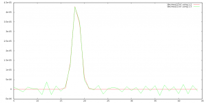
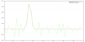
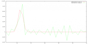
I made a few plots of the only filtered (red curve) and sigma-delta modulated and filtered (green curve) signals. The input signal was a single sample of 0.0001 in a series of zeroes (first plot) or a single sample of 0.00002 in a series of zeroes (second and third plots). I forgot to put a randomize command in the Pascal code, so the dither always has the same value at the same place.
Attachments
Last edited:
That was meOK.
Your experiments were a bit interesting. You( or someone else ) said that a modern SD algoritm is virtually impossible to understand in the time domain.
That's more or less what a have been saying all the time in a laymans words. The algorithm assures nice operation as long as you are talking about static signals.
you won't understand modern oversampled quantizers ... fully ... in the time domain. Concepts like aggressive noise shaping, and decimation filters much, much longer than the oversampling ratio (with filter coefficients well beyond the set constrained by simple averaging) ... are best understand in the frequency domain.HOWEVER ... it is wrong to conclude that this means the algorithm only works well on "static" signals. Nothing could be further from the truth ... the algorithm works just fine, on ANY bandlimited signal ... static, or dynamic ... not just DC signals.
Last edited:
Sigma Delta haters, come to my rescue!!
Marcel, the tiny pulse you showed actually took several samples. I don't know if your pascal program has some kind of oversampling/interpolation or if it's only just S/D operation.
If it's no OS involved, then it's clearly inferior to a multi bit DAC, that one would just give an output of exactly one sample. That is, with no output filter - digital or analog - a pure NOS, so to speak.
I said this before, but the true challenge would be to feed your SD algorithm with the following signal: ( at fs/2 )
0.0001
-0.0001
0.0001
-0.0001
etc...
A multibit DAC would give exactly that output in NOS mode.
If the algoritm can handle that( which I serioulsly doubt ) feed it with the following:
0.0001
-0.0001
0.0001
-0.0001
( lets say 20 samples )
then 20 zero's
repeat the pattern....
This is more like natural sound.
If you can show that it will come up with something that look remotely like a NOS multi bit DAC, yes then I will truly be a Sigma Delta fan.
Btw, I'm actually in the process of building a PCM1794 DAC in mono mode and with optional NOS operation.
....
Btw, I'm actually in the process of building a PCM1794 DAC in mono mode and with optional NOS operation.
something where I am looking for more reviews, PCM1794 in NOS operation, create thread about your progress
- Status
- This old topic is closed. If you want to reopen this topic, contact a moderator using the "Report Post" button.
- Home
- Source & Line
- Digital Line Level
- Clarification of Sigma Delta DAC operation wanted