how are measuring your ripples? I get 0,0mvac but i think its to good to be true! however!
Toroidy trafo 200VA 2x22VAC, caps are 33kuf from Cornell dubilier 380LX and MUR1560. I only have the output snubber capacitors and the Input snubber capacitor. I've finished my cheapomodo proto board yesterday and don't have an oscilloscope at my house to measure. Only next weekend.
Picture is: CRC psu feeding sony vfet diy one channel only.
An externally hosted image should be here but it was not working when we last tested it.
Hi all,
Somebody had suggested (Ades, I think) to make a generalized BoM for this PCB.
Attached is my attempt at the same. Its an excel 2010 document. The first sheet gives the schematic and silk outline. Second sheet gives the generalized BoM and third sheet gives the calculations (example) of power ratings of resistors for given assumed voltages and currents.
However I also should caution on using a generalized bom as it is just meant as a guideline and no absolute values from it to be used unless one assesses his requirements carefully and then selects the components accordingly.
Hope this is useful here to some of the beginners to ease out the component selection process. I would be glad if some one could take some time out and suggest improvements or point out mistakes.
I am also going to put this up on an online store here in India where I intend to sell pcb locally.
I still have about 18pcbs to spare here on diya from the latest batch of 50 pcb.
regards
Prasi
Attachments
Dual CRC PSU's now in Babelfish J project. With 400VA Antek 18VAC I am getting 1mV ripple no load. Pretty good - let's see what happens when 1.25amps flow. Fits a 3U Dissipante case perfectly.

Babbelfish J PCBs
@xrk does your transformer have dual centre tapped secondaries?
@xrk does your transformer have dual centre tapped secondaries?
No, running two PSU in parallel from two secondaries. Of course finding out this is not any good as I am getting a lot of ground loop hum in one channel. I just ordered dual 18vac toroidal trafos to redo this.
If you look at my pics above the way I am connecting 2 PSU boards is use a thick wire and solder the ground pins of each of the PSU boards together. Then on the lower board I connect one of the ground pin to the chassis paired with the ground loop breaker circuit. Absolutely no hum issues in this way as both the PSU boards will have only one ground connection to the ground loop breaker and to the chassis.
if you operate a centre tapped transformer feeding into a single bridge rectifier then that amplifier has the centre tap connected to the Main Audio ground.No, running two PSU in parallel from two secondaries. Of course finding out this is not any good as I am getting a lot of ground loop hum in one channel. I just ordered dual 18vac toroidal trafos to redo this.
If you repeat this for a second channel you end up with TWO connections from the centre tap to the Main Audio Grounds.
Now attach a two channel interconnect from a source that has a commoned Signal Return and you end up with a loop.
That makes for interference.
Do NOT try to use a single centre tapped transformer to power multiple bridge rectifiers.
if you operate a centre tapped transformer feeding into a single bridge rectifier then that amplifier has the centre tap connected to the Main Audio ground.
If you repeat this for a second channel you end up with TWO connections from the centre tap to the Main Audio Grounds.
Now attach a two channel interconnect from a source that has a commoned Signal Return and you end up with a loop.
That makes for interference.
Do NOT try to use a single centre tapped transformer to power multiple bridge rectifiers.
Andrew, I believe he is using a single transformer with "dual secondaries" and connecting the the two secondaries to 2 PSU boards.
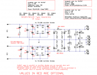
Schematic of PSU here below.
Attachments
If you look at my pics above the way I am connecting 2 PSU boards is use a thick wire and solder the ground pins of each of the PSU boards together. Then on the lower board I connect one of the ground pin to the chassis paired with the ground loop breaker circuit. Absolutely no hum issues in this way as both the PSU boards will have only one ground connection to the ground loop breaker and to the chassis.
Do you have a link to the pics please.
In my case
I have built two crc psu with mur860, 10kuf 80v. Snubber caps and resistors.
My transformer ratings are 0-35 8A and 0-35 8A.
When i connected single psu to the transformer it worked fine and the output dc voltages is around 48v
When i connected 2 psu from the single transformer diodes got blown [emoji20]
Have checked the wiring and there is nothing wrong like i pulled 2 wires from dual secondary and given it one input of each psu.
If the heatsink is not isolated it would have blown on connecting single psu, btw i tested individual module for about 20 mind each to get confirmed nothing wrong before connecting to the amp boards.
correct operation with transfo means?
Haven’t connected to amp just connected the transformer for psu
correct operation with transfo means?
Haven’t connected to amp just connected the transformer for psu
Prasi,Andrew, I believe he is using a single transformer with "dual secondaries" and connecting the the two secondaries to 2 PSU boards.
Schematic of PSU here below.
If you have four secondaries you can use two sets of those 8 diode rectifiers to create two isolated supplies for two isolated amplifiers.
If you have two secondaries you will find that duplicating the PSU to feed two amplifiers creates a loop with the source's commoned signal return.
- Home
- Group Buys
- CRC Power Supply (Class A amplifier)