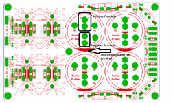
Thanks Prasi this is much better
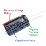
So the little red notch on the outer circle of the caps indicates -ve?
Attachments
I finished one board with total of 8 MUR860G diodes 4 per rail with TO-220 heat sinks with the 51R 1/2w resistor, 15000uf*4 caps, 0.47R 3w resistors adn 0.1uf film caps. I used thermal pads for MUR860 on each side of the heat sinks and bolted them using a screw nut. When I powered with a 0-23v 6.8A transformer I see that the LEDs glow and some sparks coming from near the heat sinks presumably from the MUR diodes. Not sure why this is happening and I could not check the DC voltage as I immediately switched off.
By the way one observation is that the metal pads of the MUR diodes each side of the heat sinks have connectivity when checked on DMM. Not sure whether is this supposed to be as I believe both the opposite diodes should be isolated. Is it because of the screw nut that is used to bolt them together to the heat sink?
Thanks in advance. Here is the pic of my build for reference.
An externally hosted image should be here but it was not working when we last tested it.
Last edited:
I finished one board with total of 8 MUR860G diodes 4 per rail with TO-220 heat sinks with the 51R 1/2w resistor, 15000uf*4 caps, 0.47R 3w resistors adn 0.1uf film caps. I used thermal pads for MUR860 on each side of the heat sinks and bolted them using a screw nut. When I powered with a 0-23v 6.8A transformer I see that the LEDs glow and some sparks coming from near the heat sinks presumably from the MUR diodes. Not sure why this is happening and I could not check the DC voltage as I immediately switched off.
By the way one observation is that the metal pads of the MUR diodes each side of the heat sinks have connectivity when checked on DMM. Not sure whether is this supposed to be as I believe both the opposite diodes should be isolated. Is it because of the screw nut that is used to bolt them together to the heat sink?
Thanks in advance. Here is the pic of my build for reference.

dont power it.
the short is due to screw holding both diodes.
you have to use a plastic sleeve like this here in xrk's build.
CRC Power Supply (Class A amplifier)
look closely.
also use a bulb tester and eye protection

Last edited:
Hmm ok got it but I may not have those right now. But I have the nylon nuts/bolts so will remove the metal nuts/bolts and use the nylon ones (screw type ones) and check it out.
yep, nylon should work.
There's a lot of parts just to the rectifier on this PSU: 4 heatsinks, 8 MUR diodes, 8 nylon shoulder washers, 4 bolts, 4 nuts, 8 silicone heatsink insulator spacers,... but the result is a bridge that can handle many amps of continuous power. Under load of 3amps these heatsinks get hot. It's amazing how small bridge rectifiers without heatsinks work - they must get pretty hot too.
Yes agree so many parts just near the diode section
I was able to find some spare nylon bushes and voila it worked and the output DC voltage is pretty stable, thanks Prasi.
I was able to find some spare nylon bushes and voila it worked and the output DC voltage is pretty stable, thanks Prasi.
An externally hosted image should be here but it was not working when we last tested it.
Looks like you have it working well now. I am waiting for MUR880's to arrive before building two more for my big Class A chassis that will hold a variety of amps depending on my mood. I will be using four 22mF 35v caps per PSU - and each will be for a monoblock with its own toroidal trafo. I am debating whether or not to add a cap array. I think they are only needed for Class AB whereas Class A has steady current draw.
Hi Pierre,
There are no boards left. However I have ordered 50 more as I have been getting some requirements through PM and for local sale. Price will be 5.3 USD per PCB. PCB will be available with me in another 18 days approx.
regards
Prasi
Here is the list
bigaudioscotto 2 nos
vj_audio 2 nos?
ajit 2 nos
Pierre 4 nos.
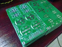
received another 50 CRC boards today.
For those as per above list and also anyone else, Please send me a PM with your name, address, postal code, Paypal address.
Attachments
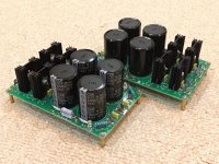
I just built up two more PSU's. This is the second gen layout and it works well. I am using 22mF 35v caps and 2x 0.47R Panasonic 3W metal film. Diodes are all MUR880's from Mouser. I have to say, these PSU's are just as complicated and time consuming to build as an amp. Nice PSU, but sure uses a lot of my stash of film caps!
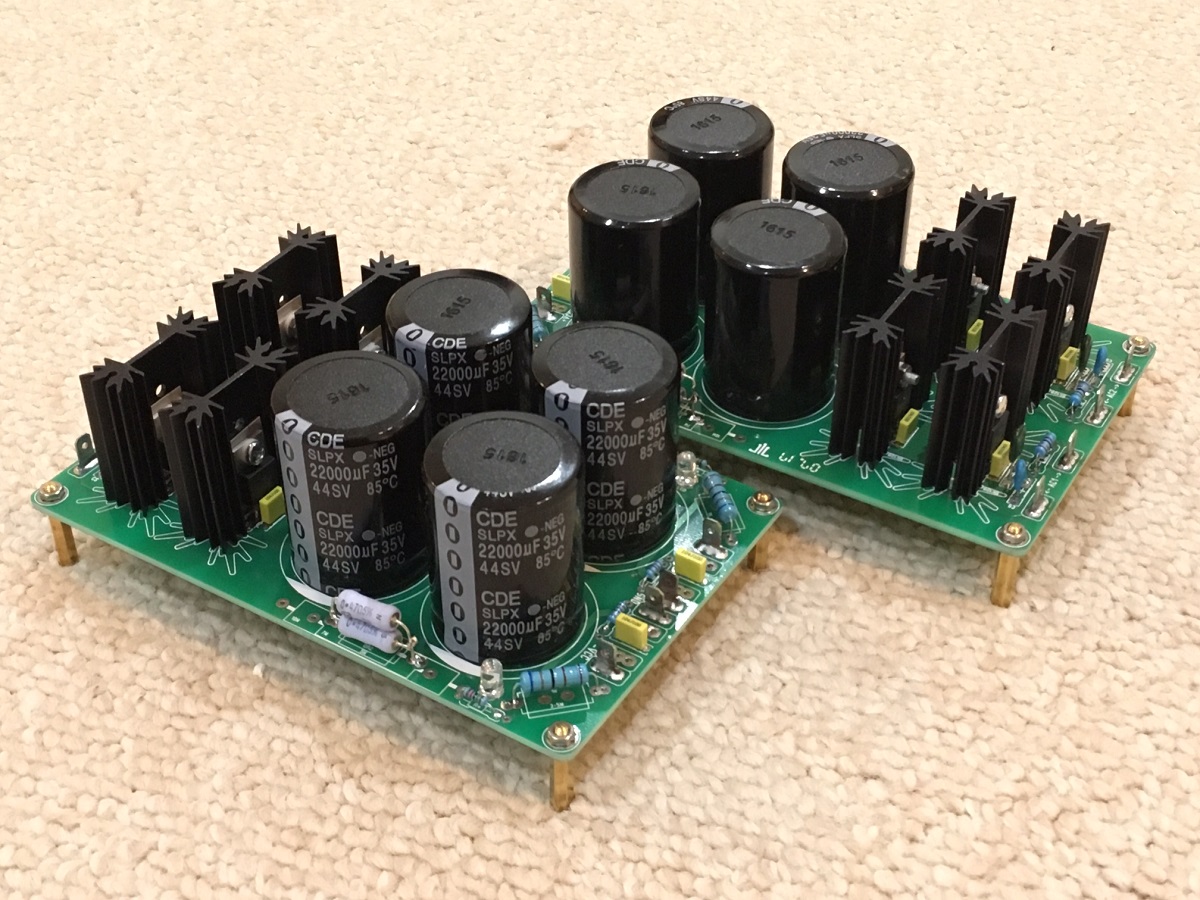
I will probably use this for my main Class A PSU for various amps from here on out. M2, DLH, F5, Babelfish J, etc...
I will probably use this for my main Class A PSU for various amps from here on out. M2, DLH, F5, Babelfish J, etc...
Attachments
Last edited:
I just built up two more PSU's. This is the second gen layout and it works well. I am using 22mF 35v caps and 2x 0.47R Panasonic 3W metal film. Diodes are all MUR880's from Mouser. I have to say, these PSU's are just as complicated and time consuming to build as an amp. Nice PSU, but sure uses a lot of my stash of film caps!
I will probably use this for my main Class A PSU for various amps from here on out. M2, DLH, F5, Babelfish J, etc...
As usual, nicely done. Yep sure does use plenty of small things like fastons, plastic sleeves, insulating pads, film caps. Etc.
Have you tried building one with Quasimodo components with default values or as per Quasimodo procedure?
Last edited:
One thing I have noticed is that the pads especially of the smaller components like the LED come off easily with desoldering/soldering couple of times with a 25w iron, otherwise very nice VFM boards
Thats strange, it would be a problem with 35um and smaller pads. However this board has 70um and comparatively big pads.
One should keep both pads heated while pulling out, if one pad is cold, it stresses that pad.
Thats strange, it would be a problem with 35um and smaller pads. However this board has 70um and comparatively big pads.
One should keep both pads heated while pulling out, if one pad is cold, it stresses that pad.
Hmm I used a single solder while heating and also underside of the PCB to pull out the LED which was reversed. So the underside pads came out but resoldering the LED with the correct orientation worked without any issues.
Hmm I used a single solder while heating and also underside of the PCB to pull out the LED which was reversed. So the underside pads came out but resoldering the LED with the correct orientation worked without any issues.
Ok I get it. Do have a look at some desoldering videos on youtube, especially by adafruit (funny guy!) and others. there is plenty of good info and plus it requires skill which comes with plenty of debugging of amplifier/pre-amp PCBs especially that have 8 pin, 14 pin IC and to-92 transistors (desoldering w/o damaging) on double sided PCB. De-soldering LM3886 soldered in small holes was a PITA the first time I did it.
Get the desoldering tools from aliexpress based on user reviews and no of orders.
You will be good to go.
BTW your PCB are shipped, also others who ordered, I shall share tracking info by tomorrow.
regards
Prasi
Dual CRC PSU's now in Babelfish J project. With 400VA Antek 18VAC I am getting 1mV ripple no load. Pretty good - let's see what happens when 1.25amps flow. Fits a 3U Dissipante case perfectly.
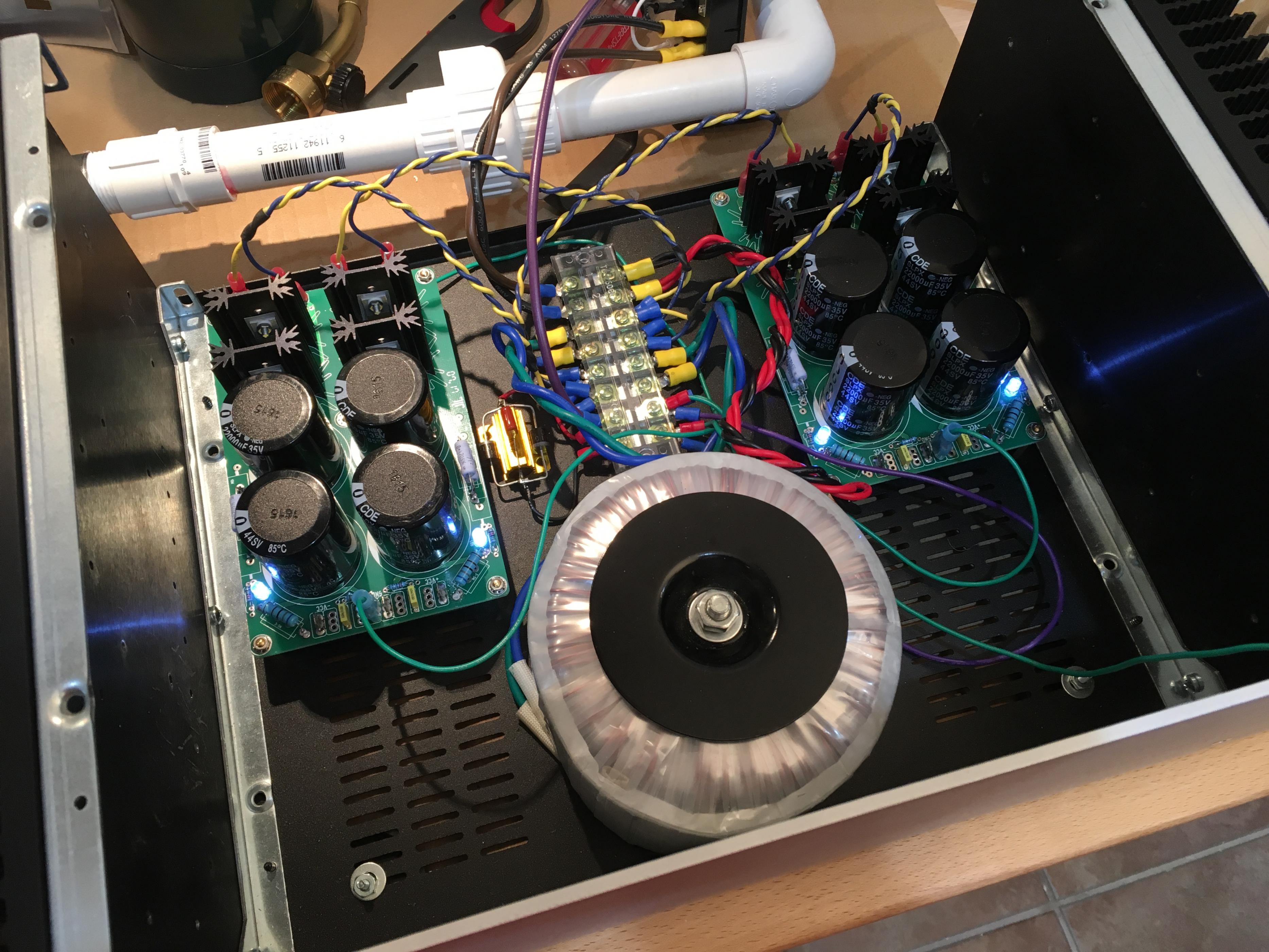
Babbelfish J PCBs
Babbelfish J PCBs
Dual CRC PSU's now in Babelfish J project. With 400VA Antek 18VAC I am getting 1mV ripple no load. Pretty good - let's see what happens when 1.25amps flow. Fits a 3U Dissipante case perfectly.
Babbelfish J PCBs
Nicely done, all the best for your Babelfish J project.!
- Home
- Group Buys
- CRC Power Supply (Class A amplifier)