I recently had a pair of PYE25 amps for service, and I really like how these KT66 amps sounded with my speakers (once they were back to life). I knew I had a bunch of KT66 tubes somewhere in my stash, so I looked what else I could find. I came back from the basement with some more KT66 that I forgot about, a bunch of 6SN7 tubes, and a pair of Electra Print 8037 plate chokes (20 mA max.). I believe these parts would make a good lineup for a mid-power push-pull amp (I should be fine with 10 to 15 Watts). I don't need a lot of gain from the amp, and I'd like to use only a little bit of global feedback.
Any suggestions for schematics, concepts, configurations? Thoughts?
Oh, and I'll need some good output transformers, primaries somewhere in the 8-10 kOhm range. Any recommendations?
P.S.: I also found a bunch of other tubes, too. Anyone interested in Philips Miniwatt EL34 metal base?
Any suggestions for schematics, concepts, configurations? Thoughts?
Oh, and I'll need some good output transformers, primaries somewhere in the 8-10 kOhm range. Any recommendations?
P.S.: I also found a bunch of other tubes, too. Anyone interested in Philips Miniwatt EL34 metal base?
Last edited:
I've build this with a few mods and it's excellent.
http://www.keith-snook.info/amplifier-hifi-schematics/Acrosound 6L6 Rebuild.pdf
Output transformers from Hammond are good, The 1650FA would work nicely.
I suggest using a separate resistor/capacitor on the power tube cathodes. I get good results with 620R/330uf.
Cheers
http://www.keith-snook.info/amplifier-hifi-schematics/Acrosound 6L6 Rebuild.pdf
Output transformers from Hammond are good, The 1650FA would work nicely.
I suggest using a separate resistor/capacitor on the power tube cathodes. I get good results with 620R/330uf.
Cheers
Thanks for suggesting this. However, I didn't just want to copy a 50 year old design. While there's nothing wrong with old designs, there have been a few developments during the past few decades that may actually be good. I quite enjoyed a good old Pye-25 amp that I had in for repair, so I used this as an inspiration and added some "helpers" that make use of those newfangled semiconductors.
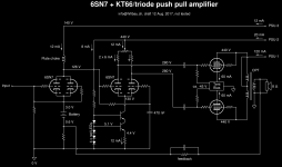
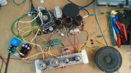
I attached the schematic I dreamed up. I also built one channel in Mc Gyver style (lots of cable ties and tape, see photo). The amp worked right from the beginning and it even sounds ok as far as I can tell so far. I think that's very strange, because I expected a loud bang and a lot of magic smoke.
The input stage is a choke loaded 6SN7, mainly because I already the choke and wanted to use it. Also, I don't need a lot of gain in my system, so the medium-mu 6SN7 is perfect here.
The phase splitter is a direct coupled long tailed pair with a CCS in its tail. The CCS improves the symmetry of the two output signals. It also makes direct coupling a lot easier, because the CCS automagically adjusts the bias voltages in the phase splitter. The idea of the pot is to tweak the (non-)symmetry of the phase splitter output in order to minimise/compensate the non-linearity of the power stage (I still have to see if/how this works).
The output stage uses fixed bias. I used a Tent bias module, which automatically adjusts the bias currents of both power tubes to the same value, so the DC magnetisation of the output transformer is minimized.
Attachments
I'm building this today. It's good for about 15W class A power and the parts are common/affordable.
The KT66 will plug in without any modifications, as will a 6L6, KT77, KT88 etc.
I didn't show the heater supply as It's stupid simple and a matter of parts on hand/preference. I personally use a Chinese switching supply for LED strips.
Cheers
The KT66 will plug in without any modifications, as will a 6L6, KT77, KT88 etc.
I didn't show the heater supply as It's stupid simple and a matter of parts on hand/preference. I personally use a Chinese switching supply for LED strips.
Cheers
Attachments

Last edited:
What's the purpose of the second 6SN7 after the phase splitter? More gain?
Correct. That's "classic" Williamson style circuitry. A common cathode voltage amplifier DC coupled to a "concertina" phase splitter. The O/P of the splitter is cap. coupled to a differential gain block that, in turn, is cap. coupled to the PP "finals". The "Achilles Heel" of Williamson style circuitry is low frequency instability. Spread the low pass poles out and use decent "iron" to obtain good results.
Spread the low pass poles out and use decent "iron" to obtain good results.
CORRECTION Spread the high pass poles out and use decent "iron" to obtain good results.
Correct. That's "classic" Williamson style circuitry. A common cathode voltage amplifier DC coupled to a "concertina" phase splitter. The O/P of the splitter is cap. coupled to a differential gain block that, in turn, is cap. coupled to the PP "finals". The "Achilles Heel" of Williamson style circuitry is low frequency instability. Spread the low pass poles out and use decent "iron" to obtain good results.
That's why I tried to avoid RC networks in my design. There are only two RC networks left (in the phase splitter, and the coupling to the power stage). It's easy to keep their poles at different frequencies. I don't really know how the battery bias behaves in terms of phase lag at it's AC/DC transition.
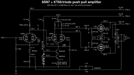
I worked a bit more on the amp today. The DC bias voltages and the AC signal levels were all spot on to what my paper-and-pen design approach gave me. The amp is nicely stable under all conditions I tried so far (no HF oscillation or motorboating). It behaves very well during start up and power down (no funny noises or pumping). The amp starts clipping at 1.95 V input (peak-to-peak), where it produces about 12 W into 8 Ohm. Frequency response (-3 dB) is about 4 Hz to 150 kHz or so (pretty darn good for such a MacGyver style tube amp, I think). A nice pet to deal with!
I attached the schematic. Comments and suggestions are welcome!
Attachments
Last edited:
CORRECTION Spread the high pass poles out and use decent "iron" to obtain good results.
Luckily I have no such LF instabilities, but that might be down to the toroid outputs. My -3db frequency for coupling caps is about 2Hz. I also don't use much feedback. Just enough to make a perfectly clean square wave at 10kHz.
Without feedback full volume is about 0.25V, with feedback it's 1V. (12db?)
Luckily I have no such LF instabilities, but that might be down to the toroid outputs.
The schematic you posted indicates a 120V:9V transformer. Is this a common garden power transformer designed for power supplies? I have never tried a power transformer as an output transformer, so I'd sure like to learn how that works.
I used a Vanderveen VDV8020 toroidal output in my amp.
The schematic you posted indicates a 120V:9V transformer. Is this a common garden power transformer designed for power supplies? I have never tried a power transformer as an output transformer, so I'd sure like to learn how that works.
I used a Vanderveen VDV8020 toroidal output in my amp.
Yes. By using a CCS in the cathode to balance the DC current in the core some toroidal power transformers work very well as OPTs (And it serves to balance mismatched tubes, too). The bigger the VA rating, the better the bass response. The actual arrangement was inspired by John Broskie of Tubecad.com and George of Tubelab.com, I've just put all the pieces together
")
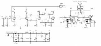
I have great results with Triad VPT18 series, which with an 8 ohm speaker reflects a 5.2k Raa. With 4 ohm it's ~1.25k. The VPT12 series is good for when you need 3k or 12k from 8 ohm. The one used in the above schematic is the VPT18-5560. (VPT18-5560 Triad Magnetics | Transformatoren | DigiKey)
The choke is actually 2 Triad C-14X in parallel, and they are cheap, too. (C-14X Triad Magnetics | Induktoren, Spulen, Drosseln | DigiKey)
And you can use this as the power transformer. (VPT230-1090 Triad Magnetics | Transformatoren | DigiKey)
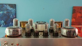
Here's a snap of the finished amp.
Attachments
Last edited:
I have great results with Triad VPT18 series, which with an 8 ohm speaker reflects a 5.2k Raa. With 4 ohm it's ~1.25k.
Could you show your formula for the primary Z. I'm using a 230/18 for the TR = 12.77. So the square = 163 x 8 =1304. A-A would be series and need to use the 230/18 ratio, correct?
Could you show your formula for the primary Z. I'm using a 230/18 for the TR = 12.77. So the square = 163 x 8 =1304. A-A would be series and need to use the 230/18 ratio, correct?
I use:
230/9 = 25.5 (turns ratio)
25.5 ^2 = 653.9 (impedance ratio)
653.9 * 8 (Voice coil impedance)
= 5224:8
Primaries in series, secondaries in parallel.
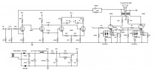
EDIT: I just saw the mistake in the posted schematic. Secondaries should be parallel.
Here is the proper schematic.
Attachments
Last edited:
I use:
230/9 = 25.5 (turns ratio)
25.5 ^2 = 653.9 (impedance ratio)
653.9 * 8 (Voice coil impedance)
= 5224:8
Primaries in series, secondaries in parallel.
Your diagram shows your secondaries in series.
Your diagram shows your secondaries in series.
I noticed, the previous post shows the updated schematic. It was modified from the 12AV5GA which uses the VPT12 in series, and I missed the change.
I noticed, the previous post shows the updated schematic. It was modified from the 12AV5GA which uses the VPT12 in series, and I missed the change.
The new diagram still shows them in series but now also has the two coils in opposite phase. Also there is no chassis ground indicated for the secondary which may affect the function of the feedback circuit.
The new diagram still shows them in series but now also has the two coils in opposite phase. Also there is no chassis ground indicated for the secondary which may affect the function of the feedback circuit.
....I'm having a bad day it seems. Originally this amp didn't have a feedback loop so the secondary wasn't grounded.
I wonder if a moderator could delete it...
Attachments
I wonder if a moderator could delete it...
I wish they'd give people a reasonable amount of time to catch mistakes before locking us out of editing. So do those toroids carry the highs well? No doubt they have the low end.
Yes the highs are excellent. When I tested it at 10kHz in a square wave I had to double check it was connected through the amp!
And according to Triad the average inductance of the primary is 175H. Very pleased with the results.
I haven't gotten a handle on the good, bad and ugly of Henry... I skipped school that day, I guess...
- Status
- This old topic is closed. If you want to reopen this topic, contact a moderator using the "Report Post" button.
- Home
- Amplifiers
- Tubes / Valves
- What to build with KT66 and some other parts?