
Try using the same basic amp, but modify it for a little less gain, and remove the negative feedback (all this may be easier said than done properly).
Ok, I cheated a bit. I simply removed the global NFB and repeated the measurements. The gain was about three times more and the THD was about ten times higher without the global NFB. I'd think that differences between different tube types would be multiplied by a similar factor. The result was that all the GEC tubes (clear glass and smoked / grey glass) gave the same harmonic distortion (about 0.14% THD). The only difference was with the (Chinese?) Groove Tubes types, where the THD was about half of the GEC value. Hmmm.
Same input level or same output level for all tests?
It looks like you auto-bias each output stage valve to the same cathode current?
From the schematic in the other thread, 475k grid leak on a KT66 is very high.
Does your input stage operating point change much with no feedback?
It looks like you auto-bias each output stage valve to the same cathode current?
From the schematic in the other thread, 475k grid leak on a KT66 is very high.
Does your input stage operating point change much with no feedback?
Same input level or same output level for all tests?
Output was always at 2.84 Vrms into 8 Ohm (1 Watt).
It looks like you auto-bias each output stage valve to the same cathode current?
Correct. 57 mA through each KT66.
Balanced currents minimize the DC saturation of the output transformer.
From the schematic in the other thread, 475k grid leak on a KT66 is very high.
I chose this value based on the LF cut off point of the power stage. I wanted to keep the different poles in the amp away from each other. What would be a better value for the KT grid leak, and why?
Does your input stage operating point change much with no feedback?
Bias voltages are the same with and without feedback. Why would they be different?
Ok, so I worked at bit more on the amp. Turns out the plate choke tends to pick up some 50 Hz hum and harmonics. I could just replace the choke with CCS and be happy, but I'd like to see how far I can take the choke. Any suggestions or hints how to reduce the hum pickup in the choke? Shielding? How?
This might sound obvious, but did you try orienting the choke differently?
Another thing I recently was made aware of was rubber supports. I think Thomas Mayer showed them to me originally. Maybe the 50Hz hum is mechanical and coming from the chassis...
Ian
Datasheet recommendation seems appropriate, unless I guess you have confirmed the grid leakage level to be 'as new'. The schematic seemed to infer fixed bias, which would then be 250k, unless you are hammering the valves.I chose this value based on the LF cut off point of the power stage. I wanted to keep the different poles in the amp away from each other. What would be a better value for the KT grid leak, and why?
The 49.9 ohm is shunted by 1k normally, so now it would be not shunted, and maybe the anode voltage has changed a bit which may then change the next stage bias point. The schematic showed 49.9 ohm, and measurements with a reasonable degree of resolution.Bias voltages are the same with and without feedback. Why would they be different?
Last edited:
Datasheet recommendation seems appropriate, unless I guess you have confirmed the grid leakage level to be 'as new'. The schematic seemed to infer fixed bias, which would then be 250k, unless you are hammering the valves.
Yes. Silly me. Thanks for pointing this out.
The amp works fine with 475k, but I'll take a look at this next time I open it.
The 49.9 ohm is shunted by 1k normally, so now it would be not shunted, and maybe the anode voltage has changed a bit which may then change the next stage bias point. The schematic showed 49.9 ohm, and measurements with a reasonable degree of resolution.
Ok, the 1k feedback resistor in parallel to the 49.9 Ohm resisitor gives a total resistance of 47.5 Ohm. With the NFB disconnected, the cathode sees 49.9 Ohm, which is only 5% different. I'd say that's negligible, and in fact the bias voltages were the same with/without the NFB connection.
This might sound obvious, but did you try orienting the choke differently?
Another thing I recently was made aware of was rubber supports. I think Thomas Mayer showed them to me originally. Maybe the 50Hz hum is mechanical and coming from the chassis...
Ian
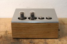
Sorry for not reporting back earlier... Changing the choke orientation did help a bit. However, the new position would have required quite some mechanical work and rebuilding stuff. Also, out of curiosity, I tried a CCS plate load in place of the choke. The CCS gave less hum, better linearity and did not limit the bandwidth of the driver stage like the choke did. The amps are playing nicely with the CCS, and I guess it will stay this way. I attached a photo.
Attachments
- Status
- This old topic is closed. If you want to reopen this topic, contact a moderator using the "Report Post" button.
- Home
- Amplifiers
- Tubes / Valves
- What to build with KT66 and some other parts?