All I can say is that it sounds fantastic and has been completely reliable since I built it.
I have a picture in my mind of an 833c amp that was not reliable!
It just leaves a smoking crater in the ground and a small mushroom cloud!
")
I use 6E5P in triode to drive GM70. Do as Magz advises, use a 100-200R carbon composition resistor from screen to anode.
I played with all the usual suspects, E180F, D3A, EF184 and so on but found I preferred the 6E5P. Of course your taste will be different from mine so be prepared to play with driver valves.
The GM70 loves grid current so if you can tolerate sand use a MOSFET source follower to drive the grid. Even if you don't intend A2 operation it helps with blocking distortion.
Merry Christmas everyone
Cheers
Matt
Matt, care to share your schematic showing grid current drive? I don't have a clue when it comes to sand....
Magz, what is the choke at the input? Why not just a resistor?
The choke doesn't need to handle the entire B+ if you wire it between the negative side of the FWB and ground.
Saw that in several Hammond Amps. I like the "not quite the way one normally sees it" moments in engineering.
showing grid current drive?
The theoretical schematic is in the #43 post of http://www.diyaudio.com/forums/tubes-valves/300831-finishing-c3m-300b-5.html.
Magz, what is the choke at the input? Why not just a resistor?
I thought it would be a nice touch in a "no expense spared" amp build. Very low DC resistance but very high AC resistance, best of both worlds for a grid "resistance". Keeps the 6E5P rock stable. Also, it should help isolate the 6E5P grid from fluctuations in the ground that could occur during operation with heavy 833 grid current.
Deafbykhorns, if you check out George's (Tubelab) web site it should all become clear:
Power Drive | Tubelab
Cheers
Matt
Power Drive | Tubelab
Cheers
Matt
The choke doesn't need to handle the entire B+ if you wire it between the negative side of the FWB and ground......I like the "not quite the way one normally sees it" moments in engineering.
I read it in an Amateur Radio Handbook a long time ago. I have used this method to use a low voltage, or unknown choke in a high voltage power supply several times. You can even stick the choke in the CT lead of the power transformer in a conventional FWCT tube rectifier power supply. If using a cap input filter the positive end of both caps go to the rectifier cathode, and one negative lead goes to each end of the choke.
I have used a mosfet PowerDrive to feed the grid of a hungry 833A. I got 200 watts at the edge of clipping on about 1600 volts with a 5K ohm OPT. Grid current hit 200 mA peaks with me cranking my guitar into it.
Don't try this at home!!!!!
Attachments
Is the power drive possible with cathode bias?
Yes, but you will still need a negative voltage source for the source resistor on the mosfet so the simplicity of cathode bias is mostly lost.
Technically it can be made to work without the negative supply by raising the grid voltage well into the positive region and increasing the cathode resistor to make the tube current the same as with ordinary cathode bias. Now you are burning up a significant amount of your power supply's energy as heat, so again another compromise.
I have a picture in my mind of an 833c amp that was not reliable!
It just leaves a smoking crater in the ground and a small mushroom cloud!
Imagine those killovolts stored on capacitor bank, and being shorted .. Basically a principle of pulsed magnetrons-radars.
megawatts peak
One Heck of a project!
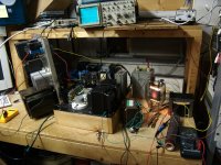
Hello Mr Midlife, Looks Like a very nice small project you finished there haha
fantastic I might attempt to build one of these mega monsters but SE Parellel feed! From my experiments so far with gm70 , from now on no more Series SE, I also would like to touch on the bottom end quality of series SE even with THE best money can buy as you have done, seems to not compare to parellel feed SE , I am not knocking your amplifier but I would be dissaponted if i spent 5 thousand on a pair of output iron to have not great bottom end and need to spend more money to fix it!.
When you have some time I would love to see some basic FR, distortion, etc test, I am curious as are many people I am sure.
all in all you did an excellent job I would be proud
Lawrence
Hello Mr Midlife, Looks Like a very nice small project you finished there
hahafantastic
I might attempt to build one of these mega monsters but SE Parellel feed! From my experiments so far with gm70 , from now on no more Series SE, I also would like to touch on the bottom end quality of series SE even with THE best money can buy as you have done, seems to not compare to parellel feed SE , I am not knocking your amplifier but I would be dissaponted if i spent 5 thousand on a pair of output iron to have not great bottom end and need to spend more money to fix it!.When you have some time I would love to see some basic FR, distortion, etc test, I am curious as are many people I am sure.
all in all you did an excellent job I would be proud
Lawrence
BTW, OPTs have both 4 ohm and 8 ohm taps. I'll be using the 4 ohm with my hot-rodded Infinity RSIIb speakers.
The secondary winding seems very thin. What is the resistance of the windings?
I thought it would be a nice touch in a "no expense spared" amp build. Very low DC resistance but very high AC resistance, best of both worlds for a grid "resistance". Keeps the 6E5P rock stable. Also, it should help isolate the 6E5P grid from fluctuations in the ground that could occur during operation with heavy 833 grid current.
Who built that grid choke for you?
Last edited:
The secondary winding seems very thin. What is the resistance of the windings?
Too low to measure with my multimeter. It reads 0.0 ohms.
Who built that grid choke for you?
It's a Lundahl LL1670.
Just clicked on the image. Toe-curling, if inventive, way to "mount" the tube.Don't try this at home!!!!!
Oh, and what voltage are your alligator clip wires rated to?
:
Bad multimetr : DToo low to measure with my multimeter. It reads 0.0 ohms.
:
Bad multimetr : D
What's the point measuring resistance on a secondary when inductive reactance comes into play? Along with capacitive coupling and winding techniques. 30-50 turns on a bobbin is nothing, I'm sure the winder has to make some compromise's with regards to wire size and layering with this size transformer.
Rout=Ri+r1/(Sr^+r2)What's the point measuring resistance on a secondary when inductive reactance comes into play?
Rout=Ri+r1/(Sr^+r2)
I'm guessing you probably wind a few transformers and critiquing the design? Please elaborate
- Home
- Amplifiers
- Tubes / Valves
- The Midlife Crisis - My 833C Amp Build