I like the attitude. Some speakers look pretty and sound awful, and others look ... well, "rough" ... but sound pretty good, and sometimes amazing. It's the nasty ol' prototypes that deliver the goods, though.
I was thinking a little more seriously about the large-format horn + 604 combo. If the diaphragms of the small-format 604 compression driver and the big compression driver are in the same plane, it'll simplify the design. It gets rid of the requirement for a full-blown crossover between the two, and they can overlap, with the 604 driver doing its thing to widen dispersion out to the Altec-specified 90 degrees. A little extra sparkle never hurt.
Lobing problems above 5 kHz are pretty much inaudible (although a nuisance to measure), so that's not a major concern. If the diaphragms are in the same plane (same distance from the listener), the crossovers can overlap as much or as little as desired .. this can be a subjective call, at the turn of a knob. To keep both diaphragms in-phase with each other, they should share the same 700~800 Hz highpass filter (but have different degrees of attenuation and in-band equalization so they phase-match with each other).
Hmm. Some food for thought here. It might actually work. Little horn + big horn.
Last edited:
Lynn,
The 604 idea is brilliant, I wish I thought of it")
See Post 1307:
To further prove your theory Lynn, I'm sure Panos "rough" speakers are sophisticates compared to my prom queens.
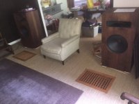
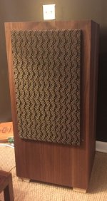
Mine sound rough but look good enough for the living room.
6.2cu ft cabs, 802B Altec drivers/ 32B Horns (metal) w Jensen P15LL woofers. Crossed over at 2kHz. Pretty ragged response and rolled off on both ends... still working on the crossover.
The grates in front of the cabinets are infinite baffle subs w 2 15" woofers per side.
file:///C:/Users/doug/Documents/Audio/My%20Speakers/IB%20Subs.jpg
file:///C:/Users/doug/Documents/Audio/My%20Speakers/mY%20DIY%20Speaker.jpg
The 604 idea is brilliant, I wish I thought of it
See Post 1307:
Has anybody explored the possibilities of using the tweeter baked into a GPA-Model 604 or any of the Altec 604 variants as a super tweeter and xover over at say... 9k and north?
You wouldn't need the supplied horn, so, maybe modify the actual horn. Or even replace the whole 802 tweeter and horn? Would love to know what that "cavity" and "channel" that the 802 occupy looks like.
It sure seems like a good real estate location to park a super tweeter.
Also... anybody have an opinion on the 604 15" woofer comparable SQ of it's 515/416 brothers.
To further prove your theory Lynn, I'm sure Panos "rough" speakers are sophisticates compared to my prom queens.
Mine sound rough but look good enough for the living room.
6.2cu ft cabs, 802B Altec drivers/ 32B Horns (metal) w Jensen P15LL woofers. Crossed over at 2kHz. Pretty ragged response and rolled off on both ends... still working on the crossover.
The grates in front of the cabinets are infinite baffle subs w 2 15" woofers per side.
file:///C:/Users/doug/Documents/Audio/My%20Speakers/IB%20Subs.jpg
file:///C:/Users/doug/Documents/Audio/My%20Speakers/mY%20DIY%20Speaker.jpg
Attachments
Marco,
considering the cost of a new pair of TAD 2001 those coaxials would be a bargain! For a truly superb top end addition the only driver I've found that can really supplement a larger compression driver is the TAD ET703, a true small format compression driver/diffraction lens combination. I will admit they are more than pricey and I'm not really a fan of diffraction lenses these things sound amazing. The only other thing I would consider are some of the small format polymer diaphragm compression drivers from Europe, but I have no experience with those.
Lynn,
As far as making the Altec 604 work wonders that only really requires a great small cone midrange to fix the poor overlap of the original cone and tiny horn. A good network and a 6 1/2" or smaller cone driver is all you really need to make them sing.
ps. The only issue with the TAD 2001, simply a JBL clone really, is that the compression drivers throat is to long which creates a very narrow exit angle. Besides that they are really nice sounding drivers with the Be diaphragms. These 1" drivers really don't give up much if anything to larger 1.4" or 2" exit drivers and the top end is superior to any larger format driver including the Radian 1.4" exit Be driver.
Last edited:
The Mantaray horn was a bit of a problem. Not big enough for the frequnecy where you'd like to cross it, and it doesn't sit down inside the cone enough to benefit from the woofer cone as horn.
The 605 with its smaller multi-cell horn actually coupled with the woofer cone better. John had pointed this out to me, and I found it to be true.
But with a midrange horn, that is not a problem. The Mantaray is plenty big enough for a true tweeter.
The 605 with its smaller multi-cell horn actually coupled with the woofer cone better. John had pointed this out to me, and I found it to be true.
But with a midrange horn, that is not a problem. The Mantaray is plenty big enough for a true tweeter.
Very true. Funny how the notion of "bargain" is always relative!Marco,
considering the cost of a new pair of TAD 2001 those coaxials would be a bargain!
I'm sure the ET703 must sound fantastic. However, they also have a rather uneven frequency response (see attachment, from the official data sheet).For a truly superb top end addition the only driver I've found that can really supplement a larger compression driver is the TAD ET703, a true small format compression driver/diffraction lens combination.
I have personally found the larger Fostex ring radiators (like the T925A units I use) to sound very clear and clean too, provided they are high-passed properly (i.e., at least 2nd order) and using good quality MKP caps (e.g., I use Jantzen Superior Z-caps).
The long and narrow internal throat is indeed a liability if one intends to use the TD-2001 as a super-tweeter. However, it also contributes (together with its "slow flare" phase plug design) to the driver's good acoustic loading down to ~400Hz. So it basically trades off some top-octave dispersion for some bottom-octave loading. Pick your poison...ps. The only issue with the TAD 2001, simply a JBL clone really, is that the compression drivers throat is to long which creates a very narrow exit angle. Besides that they are really nice sounding drivers with the Be diaphragms.
(P.S. the TD-2002 has a similar internal throat, but also a different, completely redesigned phase plug that is supposed to be better at keeping the output phase coherent to beyond 20kHz - see second attachment)
Attachments
Last edited:
...
This long digression aside, I was thinking about the two ways to implement BSC. One is passive filtering, which is subtractive (it decreases efficiency over part of the passband). The other approach is bringing in another LF driver, adjusting the lowpass filter so it compensates for BSC. This is room-dependent, so the lowpass filter will need to have taps, or be adjustable. In practice, this is a subjective adjustment, since every recording has a different set of balances in the bass region. (Recordings have a final master-balance phase, and the rooms where this is done have a variety of monitor speakers with their own set of equalizers in place.) ...
Hello Lynn
Really interesting. I believe that what you are describing would be attractive in many ways.
The obvious: it would increase the sensitivity of the loudspeaker. Instead of around 95 dB / W at 1 m for a single woofer, doubling the woofers would yield around 100. Why would this matter? If this extra sensitivity translates into an increase in perceived dynamic range, both upward and downward, then this would be very desirable in my humble opinion.
As you pointed out - baffle-step compensation is quite important. I would add that so is the overall frequency shaping of the upper-bass and lower midrange. All the effects that you mention come into play. Add to this the difficulty of meaningful in room measurements, and the design gets tedious. So having two drivers to play with would add a lot of flexibility here.
Third, there is a configuration that could address a problem sometimes forgotten in a two way with the horn on top: from a listener’s perspective, the angle at which the music comes from varies up and down according to frequency. My brain now filters this out, but some people find this objectionable, and I can understand. Personally if I were to use two woofers, then I would experiment in placing the horn between the two. The JMLC horn profile sounds best when there is some clearance around the curved portion of the mouth (at least a couple inches). To reduce beaming in the midrange of the woofers, the horn can be pulled forward, say six inches closer to the listener than the baffles. The two woofers could then be moved a little bit closer together behind the horn. This introduces a new issue though: the woofers' wave will hit and interfere with the back side of the horn’s rollover. Part of this energy will reflect back on the baffle again and disperse in the room. Perhaps the back of the horn can be treated with thick felt to reduce this issue. I think it is hard to predict how this would sound without actually testing it.
Regards - Pierre
PS I like the 604 idea too.
Last edited:
Here's my BUS ... Big Ugly Speakers. Quite a mess to look at, rather nice to hear.
...
Way to go! Thank you for sharing. I would love to hear these.
phivates, kind of an Altex 604 with an 811 horn above if it wasn't by Pioneer.
Marco, as to my poison I prefer not to use a compression driver below even 1Khz so I have no interest in large format compression drivers, they have no advantage and some disadvantages once you move up the xo point. Used this way advantage will be in favor of the shortest pancake designed compression driver with the wider throat exit angle.
I see by the drawing that they are still taking the easiest path to create the phase plug as far as the acoustical path, it's a real pity really we are still stuck with essentially what is a 100 year old design.
ps. I only used the TAD ET driver upwards from 10Khz, any wiggles in the response that high I'm not convinced are audible as long as they are not diaphragm breakup modes. A simple spike or hole that high in the program material will be imperceptible to the average person.
Last edited:
Fair enough!Marco, as to my poison I prefer not to use a compression driver below even 1Khz so I have no interest in large format compression drivers,
they have no advantage and some disadvantages once you move up the xo point.
True, there is no point in using a large-format driver if you intend to only use it above 1 kHz or even higher.
However, I don't necessarily agree on dismissing large-format drivers altogether. In my experience, there is a certain je ne sais quoi about a large-format driver used down to 500-600Hz on a big hypex horn... that's just different (in some respects I would say "better" / more "magical") than what can be achieved with a cone driver.
Agreed. All else (diaphragm, phase plug, magnet, etc.) being equal, that would probably be my pick too if I were to only use it up high.Used this way advantage will be in favor of the shortest pancake designed compression driver with the wider throat exit angle.
Well, it is somewhat different from the more "classic" concentric slit phase plug as used in the TD-2001 (and the original Lansing/JBL drivers, themselves based on the WE 594a).I see by the drawing that they are still taking the easiest path to create the phase plug as far as the acoustical path, it's a real pity really we are still stuck with essentially what is a 100 year old design.
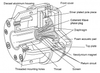
Anyhow, for something even more advanced, you'd have to look at the JBL patented "coherent wave" phase plugs as first used in the (large format) 475Nd / 2450 driver (see attachment).
Agreed that it won't be an issue at all above 10kHz. But if used down to 5-7kHz, then it might pose a bit of a problem to the crossover.ps. I only used the TAD ET driver upwards from 10Khz, any wiggles in the response that high I'm not convinced are audible as long as they are not diaphragm breakup modes. A simple spike or hole that high in the program material will be imperceptible to the average person.
Marco
Attachments
Pano, the more I look at your Big Ugly Speaker the more I like it. I like the attitude (f**k it, I'm going for it, no matter what it looks like), but I also like the combo of Big and Small horns for different frequency ranges. This is a smart way to get around the moderate 2~3 octave bandwidth of most horns, and takes care of dispersion at the same time.
My mental reservations about combining the 604 with a bigger MF horn are relieved by the idea of keeping the two compression driver diaphragms in a common plane. Although there's still vertical lobing, the leading edge of transients arrive at the same time (within a few hundred microseconds) ... and this is easily confirmed by measurement of the impulse response.
Although both compression drivers share a common 650~800 Hz highpass filter, they have separate, indepedent stepped L-pads as well as any additional highpass and equalization sections; the independent (minimum-phase) EQ helps them phase-track each other in their working passbands. If the primary function of the HF section of the Duplex is adding "sparkle", the 90 x 40 horn in the 604 Duplex can also be aimed several ways ... maybe vertically, maybe at 45 degrees, maybe horizontally in the conventional configuration.
In the bass range, the additional 416 sitting below the 604 Duplex operates in a similar way; its primary function is baffle-step and room compensation, as well as bass extension and increased power-handling. A tapped inductor working in the 150~300 Hz range, or possibly a separate power amp and room equalization, lets the additional 416 (or similar) woofer serve as overall system EQ in the bass range, without an efficiency penalty for the primary two-way system.
I guess you could call something like this a 2++ way system. The true system crossover is between 650 and 800 Hz, and the secondary drivers are there to improve and correct dispersion and the in-room frequency response. That only works if the additional drivers are time-matched to the primary drivers, so impulse response measurements are important.
Last edited:
So, which were the factors that led you to prefer the Radian compression driver in the end?
"Just" the top end extension? Or also a better timbre in the mid frequencies?
Or other reasons?
It was a tough choice but one of the drivers had to go. The factors were top frequency extension and availability of diaphragm - everything else being more or less equal.
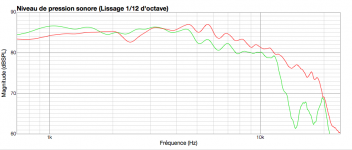
By the way John Meyer used the Yamaha JA6681A in the Meyer Sound UPA1A loudspeaker and in the 833 studio monitor. They changed it because the frequency response of the Yamaha driver tops out at 14KHz, and they needed a driver that went to 18KHz.
I found an old measurement of the two drivers in similar conditions. The green curve is the Yamaha and the red curve the unequalized Radian Be. The latter’s curve is not as smooth but it does extend well into the top end.
Subjectively with a supertweeter I had a slight preference for the sound of the Radian, but I couldn't measure nor reason why.
Attachments
I see that you ended up using similar 4th order slopes on the LP and HP branches.
From the picture you posted, however, I see a significant front-to-back offset between the woofer and the compression driver.
My question is: how did you get the two drivers to "phase track" over a reasonable frequency range around the crossover point?
In fact: did you?
In my experience, achieving good phase tracking with that kind of offset typically calls for a very asymmetrical crossover (like the TAD's 6th order LP and 2nd order HP, for instance).
Marco
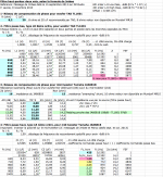
This is an area where choices have to be made. I read the JMLC, Jmbee and your posts on the topic and computed a so-called optimal electrical crossover. See an early spreadsheet below (in French sorry). It led to the first crossover I built. I also ran simulations of the filters, drivers and an exponential horn. The models were not perfect by any means, but at least the simulations showed the impact of changing the value of the offset or of any component of the filters.
What I found is that in reality I could hear the magnitude of the bumps and dips in the midrange regions more than I could hear phase or group delay - say within a 1 ms range of variations. So my attention turned to smoothing the midrange while keeping an eye on the group delay so it did not get out of hand. To keep the crossover as simple as possible (i.e. avoiding the addition of LRC circuits) I adjusted the component values or reduced filter orders where I could. I also ensured that the woofer resonance remained well attenuated. Fortunately the TAD’s resonance is fairly high in frequency and it is easy to get it at least 50 dB down.
A few words on the horn location and offset. The Azura AH425 horn is not that deep compared to others, and this particular Radian compression driver has no throat to speak of. So the physical offset you see on the picture is much shorter than on the large, classic TAD studio monitors. The TAD filter makes sense for their large offset. It is a very plain L-R filter by the way.
Various iterations of my crossover (different orders combinations) resulted in offsets that positioned the horn more behind the baffle, or more in front of the baffle, with the drivers sometimes out of phase. Crossover number 28 is just one of several sweet spots along the journey. It so happens that with drivers in phase this crossover gives an offset that positions the horn mouth in a plane with the baffle, and gives a good notch measured horizontally when the drivers are out of phase.
The notch is not symmetrical so I know there is room for improvement there. Again, I shared the filters for entertainment and make no claims as to what is a better way to design crossovers. Thanks for asking Marco.
Attachments
The grates in front of the cabinets are infinite baffle subs w 2 15" woofers per side.
Respect!Originally Posted by ogie View Post
The grates in front of the cabinets are infinite baffle subs w 2 15" woofers per side.
It gives literal meaning to the phrase 'subterranean bass'!
LOL, glad you like it - I was a little embarrassed to post the photo.Pano, the more I look at your Big Ugly Speaker the more I like it. I like the attitude (f**k it, I'm going for it, no matter what it looks like)
That setup was fun to play around with and probably taught me a few things. As my crossover was digital, no problem getting the various horns aligned in time. Of course it would be better to physically align them for better power response, but this was just big fun. I didn't have it long, it was replaced with an A7-500 that quickly morphed into an A5 with 10 cell horn and bullet tweeter.Yes, yes. Just supplementing the ends of the spectrum where help is needed. The main show is still the 15" woofer and midrange horn. Getting it all lined up would be the tricky part, I suppose.I guess you could call something like this a 2++ way system. The true system crossover is between 650 and 800 Hz, and the secondary drivers are there to improve and correct dispersion and the in-room frequency response. That only works if the additional drivers are time-matched to the primary drivers, so impulse response measurements are important.
Baffle step compensation
In post #14539 Lynn gave a comprehensive overview of the various effects to be considered when applying baffle-step compensation. This was as clear a description as I have read.
In practice there is a lot of trial and error needed for getting this compensation to sound right. And no quick way to shortcut this process other than messy room measurements and listening. For what it’s worth, here’s my finding.
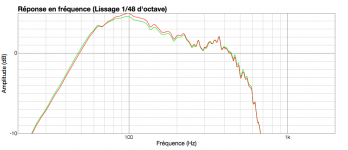
For my medium sized room, the near field response shown below was subjectively satisfactory for a paper cone that is 12.25 inches across mounted in a sealed box having a 20 inches wide baffle. The response using a solid-state push pull amplifier (high damping factor) is shown in red, and a single ended tube amplifier (low damping factor) in green. We’re looking here at a gradual 3 dB between 100 and 200 Hz, and another 1 dB between 200 and 400 Hz. This is a bit more than I thought would be needed. As Lynn and others pointed out, a second driver comes in handy to achieve this additively.
Personal taste and the room are big factors of course, so your mileage may vary.
In post #14539 Lynn gave a comprehensive overview of the various effects to be considered when applying baffle-step compensation. This was as clear a description as I have read.
In practice there is a lot of trial and error needed for getting this compensation to sound right. And no quick way to shortcut this process other than messy room measurements and listening. For what it’s worth, here’s my finding.
For my medium sized room, the near field response shown below was subjectively satisfactory for a paper cone that is 12.25 inches across mounted in a sealed box having a 20 inches wide baffle. The response using a solid-state push pull amplifier (high damping factor) is shown in red, and a single ended tube amplifier (low damping factor) in green. We’re looking here at a gradual 3 dB between 100 and 200 Hz, and another 1 dB between 200 and 400 Hz. This is a bit more than I thought would be needed. As Lynn and others pointed out, a second driver comes in handy to achieve this additively.
Personal taste and the room are big factors of course, so your mileage may vary.
Attachments
In post #14539 Lynn gave a comprehensive overview of the various effects to be considered when applying baffle-step compensation. This was as clear a description as I have read.
In practice there is a lot of trial and error needed for getting this compensation to sound right. And no quick way to shortcut this process other than messy room measurements and listening. For what it’s worth, here’s my finding.
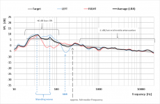
With my system & room (single 15" woofer in 60cm-wide box, placed right up against the front wall), and without any baffle step compensation at all in the passive crossover, by averaging the Left and Right speaker responses (*) I get a relatively smooth 6dB "shelf" lift below ~100Hz, which sounds just about right with most recordings (cf. Olive et al., "Listener Preferences for In-Room Loudspeaker and Headphone Target Responses").
(*) The reason for the rather different L vs R responses is due to the asymmetric positioning w.r.t. the side walls. Unfortunately, this couldn't be avoided. However, luckily, below 100Hz or so the bass frequencies in most recordings are fundamentally centred (i.e., mono), so the L+R average is all that matters.
Attachments
Thank you for sharing Marco. Very cool.
Well my speakers too are in asymmetric positions with respect to the side walls. C’est la vie.
Your plot prompted me to search my archives and guess what... I found some measurements of early prototypes that I temporarily placed close to the wall before adding baffle step compensation. I thought it would be fun to compare.
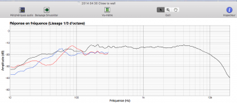
In the plot below, left is blue, right is red, and black is the combined response at the listening position of both speakers playing at the same time.
Caveats: This is not where the speakers are normally positioned. And this not the filter I now use and shared above. I think these must be the Yamaha drivers by judging the high end roll off. See how even their response is in the midrange.
A bit like in your room Marco, the dips introduced by my room are at different frequencies for the left and right speakers. I like to think that this is a positive.
In any case the low end did not sound as bad as it looked. But there simply wasn’t enough of it for me.
Well my speakers too are in asymmetric positions with respect to the side walls. C’est la vie.
Your plot prompted me to search my archives and guess what... I found some measurements of early prototypes that I temporarily placed close to the wall before adding baffle step compensation. I thought it would be fun to compare.
In the plot below, left is blue, right is red, and black is the combined response at the listening position of both speakers playing at the same time.
Caveats: This is not where the speakers are normally positioned. And this not the filter I now use and shared above. I think these must be the Yamaha drivers by judging the high end roll off. See how even their response is in the midrange.
A bit like in your room Marco, the dips introduced by my room are at different frequencies for the left and right speakers. I like to think that this is a positive.
In any case the low end did not sound as bad as it looked. But there simply wasn’t enough of it for me.
Attachments
Last edited:
- Home
- Loudspeakers
- Multi-Way
- Beyond the Ariel