Dan,
I would put it in a slightly different form:
In the original design, with LM318, and both C9 and C13 present:
At DC level the +/- input pins of the opamp had seen a slightly unbalanced situation, with 100k/ 12k on each, respectively. This, and the decreased DC gain (to unity) had blocked output offset.
At audio frequencies the +pin got to see the feedback impedance, 390ohm//12kohm=~350ohm
The -pin got to see the source, the generator output impedance, +R13, so usually about ~4kohm, in case of low generator impedance, which was the 'recommended' option prescribed by Mauro.
But in case of a nice & healthy, standard value 47kohm--100kohm input potentiometer, the -In gets to see from 16kohm (47kohm pot half course) to 29kohm (100kohm half way).
So there is a notable imbalance for the dynamic input impedances showing up on the input pins;
Furthermore, only the fact of high source impedances presented to the opamp can generate common mode distortion, like for example in the case of !even Fet ! input amplifiers: the input device Cdg, or with transistors the Ccb is strongly level dependent.
The extra 'selling feature' with the OPA827 (& OPA1641) is that properly this problem- the input part inverse capacity as a function of level - is greatly 'tuned out'.
I had been getting curious about this fact, and had setup some measurements, to be presented..
Sorry for my blabbling -- here is a quote for you, in full extension from Johnc124 here, because I had already linked to it but maybe was not so easily noted..
Ciao, George
I would put it in a slightly different form:
In the original design, with LM318, and both C9 and C13 present:
At DC level the +/- input pins of the opamp had seen a slightly unbalanced situation, with 100k/ 12k on each, respectively. This, and the decreased DC gain (to unity) had blocked output offset.
At audio frequencies the +pin got to see the feedback impedance, 390ohm//12kohm=~350ohm
The -pin got to see the source, the generator output impedance, +R13, so usually about ~4kohm, in case of low generator impedance, which was the 'recommended' option prescribed by Mauro.
But in case of a nice & healthy, standard value 47kohm--100kohm input potentiometer, the -In gets to see from 16kohm (47kohm pot half course) to 29kohm (100kohm half way).
So there is a notable imbalance for the dynamic input impedances showing up on the input pins;
Furthermore, only the fact of high source impedances presented to the opamp can generate common mode distortion, like for example in the case of !even Fet ! input amplifiers: the input device Cdg, or with transistors the Ccb is strongly level dependent.
The extra 'selling feature' with the OPA827 (& OPA1641) is that properly this problem- the input part inverse capacity as a function of level - is greatly 'tuned out'.
I had been getting curious about this fact, and had setup some measurements, to be presented..
Sorry for my blabbling -- here is a quote for you, in full extension from Johnc124 here, because I had already linked to it but maybe was not so easily noted..
In my opinion JFET inputs really come in handy in a few places...--
The second application where I believe JFETs are useful is right after the RCA jack on the audio input. The low input bias current of a JFET input lets you use high resistor values after an AC coupling capacitor, decreasing the necessary value of the coupling capacitor. JFETs also have the useful benefit of being more resistant the EMI/RFI effects.
Volume control gets a bit more interesting. If a higher value potentiometer is used (which already isn't a great option for noise reasons) then the potential high source impedance at the input of an older JFET amplifier will produce LOTS of additional distortion if the op amp is configured as a buffer. Here's where the older OPA134s and OPA604s really fall apart. CMOS amplifiers like OPA1652 and OPA1688 provide performance with high source impedance comparable to older dielectrically isolated JFET input amplifiers like the OPA627. Even better, newer DI JFET amplifiers like OPA1642 and OPA827 provide fantastic performance in these applications.
JFET types are also useful in DC servo loops for power amplifiers, but now I think the advantage goes to newer CMOS types for those applications. OPA192 makes an excellent DC servo for example.
Ciao, George
Last edited:
Marco,
Thanks for your 'modest' report..")
As someone who had the fortune to be able to follow your adventures, I would like to confirm that You had been really measured and modest here
But would like to add, maybe not widely known, that your FE and friends Evolution modules are first class equipped, highest level BOM realizations, from already before..
Ciao, George
Thanks for your 'modest' report..
As someone who had the fortune to be able to follow your adventures, I would like to confirm that You had been really measured and modest here
But would like to add, maybe not widely known, that your FE and friends Evolution modules are first class equipped, highest level BOM realizations, from already before..
Ciao, George
Hi all
I can share my experience
I've fitted Opa827 , C9 is returned in my capacitor bag and Rin now is 330K, for all this mods i have to thanks Joseph. For who use Cin, now the C can go down to 330nF.
The result is wonderful, especially with my LDR, detail, dinamic, punch and soundstage are first class, the sound is free of compression, smooth and gorgeous ...and like Unixman said, no more needs of Pre or Buffer, just a volume regulator.
This mods raise FE ( IMHO) in the olimpus of Amplifier...I tried FE versus Gryphon, McIntosh and other amps, the FE was preferred ( by owners of Gryphon, Mc etcetera, not just by me )
For who have speakers with low sensibility and low impedance, I can suggest to try 4 FE , 2 for High and 2 for low frequency ( if speakers have double connection )
With this configuration i have drove Penaudio Chara Charisma, Merlin MMx without problems and with a stunning results.
Ciao
Marco
Last edited:
Dan, my pleasure.
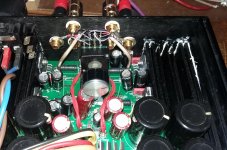
Here it is my temporary (read:ready for the eternity..) application of a pot, right on the input connectors, realized with short leads, small extra capacitive load between amplifier input and pot wiper.
This way I have my complete integrated amp, waiting for the direct connection of a source, like a Dac.
Although because of the relatively high value of potentiometer impedance (47kohm) I can connect peacefully also my tube-buffered PCM63 dac..
But, I would like to underline: personally I feel happy with this solution, for now. But I'm very far from saying this a generally recommendable solution. In fact, trying in different setups, we have heard some very fine sounding preamp, too, like the Conrad Johnson of our great Audiodan..
Attachments
Like so many of You, I had been extensively using my great little DCB1 pre with great satisfaction both for listening in the standard system, and for listening to the different amp modules under test.
Reading the description of Johnc124 quoted previously, i had to ask: but what about the input fet's Cdg capacitance in the DCB1? Do they not show the same kind of distortion problem like it's described here:
The SK170 fets in the DCB1 are doing exactly what is described here; they read out the moderately high output impedance of the volume control pot placed on the input. This is the purpose of the whole thing; they are supposed to do it much better than a bipolar input buffer; and they do it very good, indeed.
But how good it is, in reality?
So I decided to make a little quick try:
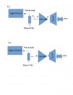
I had prepared two configurations, to be tested in sequence.
See test setup attached.
In case a.) the buffer input -output level is A magnitude, with a low source impedance, because the potentiometer is set to full max extreme. The only impedance present is that of the generator (soundcard)
In case b.) the generator outputs twice the level, 2A. The pot is set to half course, (max output impedance, in our case 7.5kohm for a 30kohm pot)
Reading the description of Johnc124 quoted previously, i had to ask: but what about the input fet's Cdg capacitance in the DCB1? Do they not show the same kind of distortion problem like it's described here:
Volume control gets a bit more interesting. If a higher value potentiometer is used (which already isn't a great option for noise reasons) then the potential high source impedance at the input of an older JFET amplifier will produce LOTS of additional distortion if the op amp is configured as a buffer.
The SK170 fets in the DCB1 are doing exactly what is described here; they read out the moderately high output impedance of the volume control pot placed on the input. This is the purpose of the whole thing; they are supposed to do it much better than a bipolar input buffer; and they do it very good, indeed.
But how good it is, in reality?
So I decided to make a little quick try:
I had prepared two configurations, to be tested in sequence.
See test setup attached.
In case a.) the buffer input -output level is A magnitude, with a low source impedance, because the potentiometer is set to full max extreme. The only impedance present is that of the generator (soundcard)
In case b.) the generator outputs twice the level, 2A. The pot is set to half course, (max output impedance, in our case 7.5kohm for a 30kohm pot)
Attachments
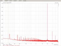
As visible, the buffer sees the same input level for both cases; but it is presented with a low source impedance (~500ohm) in the case a.)
While the same signal again, but with a moderately high source impedance in case b.) (.5k + 7.5kohm=8kohm)
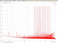
And here there are the observed distortion levels produced by the setup in both cases: (at a ~450mV rms level at 10kHz, for both cases)
First a.) then b.)
One can observe a distortion rise of ~6times, in case of the higher input impedance in front of the DCB1.
While the same signal again, but with a moderately high source impedance in case b.) (.5k + 7.5kohm=8kohm)
And here there are the observed distortion levels produced by the setup in both cases: (at a ~450mV rms level at 10kHz, for both cases)
First a.) then b.)
One can observe a distortion rise of ~6times, in case of the higher input impedance in front of the DCB1.
Attachments
Last edited:
Ok, one could say: the levels are nice and low anyway, why should we care at all?
I can not respond to this question. But would like to show from a different point of view:
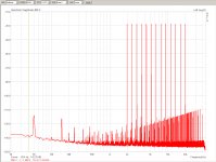
How does this same test look like with a multitone signal?
Again, case a.) first, then b.)
I can not respond to this question. But would like to show from a different point of view:
How does this same test look like with a multitone signal?
Again, case a.) first, then b.)
Attachments
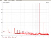
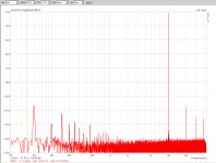
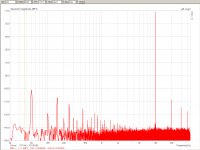
Finally, here it is the same test, but in place of the DCB1, the Evolution amp with OPA827 in input is used. Obviously with it's ~30dB gain, so the output level is high.
Case a.) here is the same, gen level is A, source impedance is ~500ohm.
Case b.) here it is with a 47kohm pot at middle position, gen at 2A level, source impedance is .5kohm+~12kohm=12.5kohm (so it is worse, higher than with the DCB1)
First is case a.) then case b.), 12.5kohm source imp.
The distortion at 10kHz is just the same; the lower hum components instead are slightly higher with the higher input impedance.
Attachments
Last edited:
Please pardon my ignorance, does jumper J1 have some special functionality?
It is shown on the PS schematic, connected to the '-' of C201 and to the ADJ leg of IC201.
Hi Alex,
I only have older pcb, v1.2, but assuming J1 is the same on the newer boards, it simply connects the negative voltage from the raw power supply to the input of the regulated power supply. A jumper is used instead of a trace because the layout requires it to cross all of the other power supply traces. A trace could be put on the bottom, but it would have cut up the ground plane. Dario chose to keep the ground plane continuous as best practice design. Having a jumper may have a small negative effect, but the current in the regulated supply is low, so it seems like a good choice. Most guys just use resistor lead material that they have cutoff to make J1 and it works well.
Can anyone confirm that J1 is the same on new boards?
Jac
Marco,
Thanks for your 'modest' report..
As someone who had the fortune to be able to follow your adventures, I would like to confirm that You had been really measured and modest here
But would like to add, maybe not widely known, that your FE and friends Evolution modules are first class equipped, highest level BOM realizations, from already before..
Ciao, George
George,
You know, I'm going crazy for this Amplifier
Yes, my modules ( FE and EVO ) are highly equipped in regards of components but... Are last yours mods who have launched my Modules straight to the top!
Before your mods, there is always something missing for my old and misused ears and something disturbing in sound, a little bit of sense of compression ( I can't explain better, sorry ).
The sound now is perfectly balanced between frequencies, and these little bit of sense of compression there's no more.
All my friends who listened my FE/EVO, only thing they said is WOW! And me too the first time I've listened FE after your mods
So, George, all this is about your research
Reddite quae sunt Caesaris Caesari ,😀
Ciao
Marco


We are honored, your Imperial Majesty.
Humbly, your servant,
Jac
My good Lord, I request that You shall continue in your faithful services !
Jokes apart: thank you, Marco, you know I value much your opinion.
But If I may choose, I think I would rather be a Janitor. And even at that, I could only be a Vice-Janitor, given that this is Dario's thread and achievement, principally.
I'm serious about this Janitorship: while I had always enjoyed enormously the beautiful,democratic and creative atmosphere in this thread (due to all of you, and the righteous governance of Dario..), still
technical projects like this, where things can explode and take out paper cones... need some less democratic and more technocratic maintenance, appunto, a Janitor
Ciao, George --- alias F. Joseph K
(hmmm.. does it not look like an F word??)
Great stuff. I'd be curious to see measurements of an LM318 amp being fed by high and low impedances.
Dan, yes, it is on my list. These days I will have again an amp in original config.
Aso would be nice to see what the others are capable of: ADA4898, OPA627 etc.
But some good information is already out there:
fet/cmos opamps tested similarly:
http://www.diyaudio.com/forums/vendor-s-bazaar/283672-audio-op-amp-opa1622-9.html#post4636374
bipolar opamps :
http://www.diyaudio.com/forums/vendor-s-bazaar/283672-audio-op-amp-opa1622-10.html#post4637092
OPA827 & OPA1641
http://www.diyaudio.com/forums/anal...pedance-jfet-input-op-amps-4.html#post4129482
Ciao, George
- Home
- Amplifiers
- Chip Amps
- My_Ref Fremen Edition - Build thread and tutorial