It's not an oscillation. The tilted baseline in the FFT is caused by the transient response of the coupling cap. Short over the cap and recalculate. Also start recording the data from 10 ms rather than 0 ms to give the simulation time to get to steady state.
First, thank you for your attention!
Although, even changing the values did not get better results in Spice.
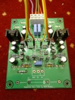
Anyway, mounted. And the sound is good!
But ... strange peaks. (60hz, 180hz, 300hz ...)?

Will it come from the power supply?
Attachments
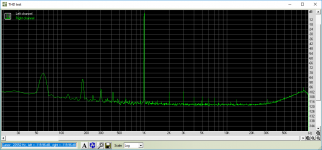
Yes, the circuit must connected to the chassis or there will be hum (your peaks at 60, 120, 300 Hz). Your RIAA analyzer data also shows a noise baseline of about -118 dB, and some small peaks at 2, 3 kHz and higher. Probably those are all just the limits of the soundcard, not the Sapphire. Your audio measurement system appears to be running in 16 bit mode. It's a good idea to measure the loopback condition (soundcard output -> soundscard input) as a baseline to compare against.
Sure, I don't see any problems doing that.
The Sapphire looks like 50k resistive load so far as the driving stage is concerned. Very easy to drive.
ok. But can I directly connect the differential output of the dac?
Skip the out-, and use only the out +?
How would the relation of R2 and R3x be for this purpose?
I'm not able to get a clear idea of what you want to do exactly. As a circuit block, the Sapphire looks like a (current feedback) op amp, you can do whatever you'd be able to do with an 8 pin DIP single CFA IC. Most DAC output stages use three op amps, two I/V converters and a balanced->single ended output stage. It's a bit out of my area, but I don't think CFA circuits will work very well in IV roles, as the DAC and the CFA may place conflicting demands on the value of the feedback resistance.
AD844 has a Zin of 65R in that application, plus low internal bias.
Depending on the DAC, you need quite a few in parallel.
You can always build discrete :
http://www.diyaudio.com/forums/digi...-minimalistic-iv-converter-5.html#post2718740
and the following ~10 posts.
Patrick
Depending on the DAC, you need quite a few in parallel.
You can always build discrete :
http://www.diyaudio.com/forums/digi...-minimalistic-iv-converter-5.html#post2718740
and the following ~10 posts.
Patrick
My main question is that my signal source is a dac with voltage output.
In line output, I have 1.4Vp at -6dbFS and 2.8Vp at 0dbFS.
I wanted to know if I can enter this swing so high and balance through the gain resistors (R3 / X and R2). If the resistor is yes, what would be more appropriate to maintain the impedance of 60 ohms in charge.
Or if I really need to decrease the input gain to around 250mvp as it is shown in the spice.
I hope you understand, sorry for my English.
Best Regards.
You will configure the Sapphire with the minimum gain of 6 dB. To get line level output you must set the DAC to output 1 V rms (1.4 V p, -6 dB FS) and that will give you standard 2 V rms (2.8 V p) on the Sapphire output.
That should work fine.
The Sapphire clipping voltage is about 7-8 V, so even running the DAC output at 2.8Vp (2 V rms) will not cause an overload provided the Sapphire gain is 6 dB as the maximum swing will be less than 6 V. The line output will be very "hot" though, well above standard line level.
That should work fine.
The Sapphire clipping voltage is about 7-8 V, so even running the DAC output at 2.8Vp (2 V rms) will not cause an overload provided the Sapphire gain is 6 dB as the maximum swing will be less than 6 V. The line output will be very "hot" though, well above standard line level.
Congratulations, RJM, this circuit is very good! I've only been listening for about 30 minutes, but so far the sound is excellent! I'm very surprised by the balance between the mid-range and treble, both are present, but neither overpowers the other. It also has a certain "presence" that I've not heard before, hard to describe. Looking forward to some longer sessions late Fri and Sat when the house is quiet.
Because by favorite headphones are 26R, I upped the bias resistors (R11, R12) to 270R. The spice models predicted ~65ma, while in-circuit measurements show 50ma. I also cut a trace and tacked a 1K series resistor in front of the input cap (C1), my ears tell me my portable X1 player does not like capacitive loads. Somehow I mixed a 15V zener with the 12V zeners and had to fix that. Otherwise everything else is as noted in the BOM, "closed loop" with 3X gain, voltage/currents as expected. Bias quickly stabilizes at 1mA or less.
I like the way it sounds. Thanks for sharing and for providing boards.
I agree...the 4.1m sounds quite good. This is the first "Sapphire" I've built.
I'm using my example as preamp with 6dB gain and much lower bias.
I purchased the boards, matched Zeners and matched input transistors directly from Richard.
Pricing for everything was very reasonable and I received everything much sooner than I expected.
Next, I would like to try the "open loop" configuration with 6dB gain along with a couple of different brands of 1uF input caps.
Hi guys,
A quick comment on Mike's build, re.
C1 does not present a capacitive load. The load impedance seen by the source consists of the series sum of C1, R1, and [a bunch of stuff including the input transistors Q1,2 but effectively R3 in parallel with R4] or about 50 kohms added to the reactance of the capacitor Xc = 1/ (2 pi f C) which at audio frequencies vanishingly small. The input of the Sapphire just looks like a 47k resistor, in other words, and adding a 1k resistor in front C1 only duplicates the existing series resistor R1. You could have obtained exactly the same result by increasing the value of R1 from 1k to 2k. (which does do something - that resistance forms a low pass filter with the input capacitance of the transistors, more resistance means a lower cut off frequency ... though the change only affects radio frequencies, aka you made a slightly stronger RFI filter.)
- just wanted to nip that one in the bud so to speak
I look forward to hearing what you think of the sound again after it's all settled in.
@ammel: Glad to hear the transistor/Zener matching was helpful to you!
A quick comment on Mike's build, re.
I also cut a trace and tacked a 1K series resistor in front of the input cap (C1), my ears tell me my portable X1 player does not like capacitive loads.
C1 does not present a capacitive load. The load impedance seen by the source consists of the series sum of C1, R1, and [a bunch of stuff including the input transistors Q1,2 but effectively R3 in parallel with R4] or about 50 kohms added to the reactance of the capacitor Xc = 1/ (2 pi f C) which at audio frequencies vanishingly small. The input of the Sapphire just looks like a 47k resistor, in other words, and adding a 1k resistor in front C1 only duplicates the existing series resistor R1. You could have obtained exactly the same result by increasing the value of R1 from 1k to 2k. (which does do something - that resistance forms a low pass filter with the input capacitance of the transistors, more resistance means a lower cut off frequency ... though the change only affects radio frequencies, aka you made a slightly stronger RFI filter.)
- just wanted to nip that one in the bud so to speak
I look forward to hearing what you think of the sound again after it's all settled in.
@ammel: Glad to hear the transistor/Zener matching was helpful to you!
Last edited:
Hello, gratings from Poland!
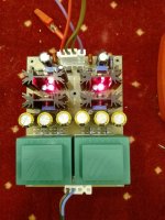
I have just build my Sapphire 41m and it is working quite well.
I have used BC550C and BC560C from Fairchild , (all from group C, matched Q1, Q2 with gain 650 and all the rest with gain 560) and for Q13, Q14 2SA1220A and 2SC2690A. (just what I had in my drawer from previous builds)
I haven’t install Q15,Q16 and zeners, as I used stabilised power supply based on two LT317 – the design described is on this page: Using 3-pin regulators off-piste: part 4
I even didn’t try to use build-in stabilizer based on Zener output – for my experience the quality of power supply is always impacting the final build and the stabiliser build on two cascaded LT317 is performed outstandingly as headphone power supply. The rectifiers are fast diodes BYV27 and filtration is 3x2200uF for each rail . I can set input voltage up to 18V, but decided to use +/- 12V. I used 4 small transformers 6VA with one secondary 18V AC each. (so the total used are 4 mini transformers, 8xLT317 and 12x2200uF)- power supply section takes more space as the amplifier itself.
For R6 I used 1k potentiometer and it is more than enough.
With default BOM parts for all the resistors I had bias of about 40mA, changing R17, R18 to 3R3 the bias went up to 65mA and finally with 2R2 settled on 98mA.
The heatsink temperature is about 50 C degrees and I thing I will keep it this way. The power supply works better if the output current is at least 100mA
One channel is open loop the other is closed , both are stable.
I didn’t listen the amp much, just did all the measurements. It is burning–in and in a few days will do the leastning tests. The main headphone I intend to use are Senheisers HD600 , but will also test it with Grado SR325.
Attachments
Where did you get the board for the LT317 power supply?
It's single side DIY, based on the design from the acoustica page. The PCB were meant for DAC, but it is also great for headphone - it grants stable power supply with very low noise and short-circuit protection built-in.
I can light up 12V 5W bulb from +12V rail (so to stress 6VA transformer to the maximum) with -12V left alone with 100mA current , and the output voltage of power supply will not change noticeably - it can led to change the offset of the amp of about 10mV, and probably the reason for this is the weak transformer that drops to 17.5V AC. Such disproportion of the load to +12 and -12V will never occur in real life, it is just the worst case scenario being tested here.
I even didn’t try to use build-in stabilizer based on Zener output – for my experience the quality of power supply is always impacting the final build and the stabiliser build on two cascaded LT317 is performed outstandingly as headphone power supply.
Actually, the Z-Reg most likely has lower broadband output noise by virtue of C6,7 over the reference voltage D1,2 and the absence of any kind of error amplifier.
For R6 I used 1k potentiometer and it is more than enough.
Thanks for that information. The power supply you are using almost certainly has higher absolute accuracy than the Zeners, so the DC offsets are more tightly controlled and less adjustment range is needed on R6.
With default BOM parts for all the resistors I had bias of about 40mA, changing R17, R18 to 3R3 the bias went up to 65mA and finally with 2R2 settled on 98mA.
I felt the more elegant method to adjust the bias current was by changing the values of the bias network R11,12 rather than the emitter resistors R17,18, but it comes out to the same thing more-or-less.
/R
I felt the more elegant method to adjust the bias current was by changing the values of the bias network R11,12 rather than the emitter resistors R17,18, but it comes out to the same thing more-or-less.
I agree, that would be more elegant and the output transistors would be more happy to get more base current.
This is by no means the final build. I wanted to quickly start it up to measure it and discover the potential of the design, hence the use of regulated power supply that I already had available and the quick hack of replacing R17, R18 did the trick. I was able to test all the parts I used and evaluate the amp.
In the final assembly I will mount them under PCB and use the case as heatsink.
I ordered "1907A Full Aluminum Headphone Amplifier Chassis" from alliexpress but it will take some time till I get it from China.
I already like the amp and I'm quite happy that I build it. It is very simple, with all parts easy to source, yet effective and pleasant to listen to.
I will post a photo of a finished amp when ready.
- Home
- Amplifiers
- Headphone Systems
- RJM Audio Sapphire Desktop Headphone Amplifier