...to publish it as an LS app note if it works out ...
Even if it has a NatSemi OTA as multiplier?
")
I wasn't able to find an AD equivalent to the LM13700 but I think the LT1228 would work and keep it in the family.
I have little experience of OTAs, any practical advice I should know?
Thanks once more for the offers, I'll PM you once I am closer to an actual layout.
Best wishes
David
Last edited:
Why keep the AGC in the analog domain? AD>logic>DA might solve issues like ripple and settling time. Why rely on 1) funky parameters of light bulbs or thermistors and 2) analog filtering shortcomings.
Note: just barged into this thread and only had a cursory look at it, so this suggestion might have come up already. Or I may be missing the point completely.
Note: just barged into this thread and only had a cursory look at it, so this suggestion might have come up already. Or I may be missing the point completely.
Why keep the AGC in the analog domain? AD>logic>DA might solve issues like ripple and settling time. Why rely on 1) funky parameters of light bulbs or thermistors and 2) analog filtering shortcomings.
Note: just barged into this thread and only had a cursory look at it, so this suggestion might have come up already. Or I may be missing the point completely.
No your not missing the point.
I was done in my oscillator quite a few years ago and I build one for Richard about a year ago too. Works very well.
Even if it has a NatSemi OTA as multiplier?
I wasn't able to find an AD equivalent to the LM13700 but I think the LT1228 would work and keep it in the family.
I have little experience of OTAs, any practical advice I should know?
Thanks once more for the offers, I'll PM you once I am closer to an actual layout.
Best wishes
David
I don't think linear systems (jfets) is directly associated with linear technology (IC's now part of AD)
I don't think linear systems (jfets) is directly associated with linear tech..
I believe you are correct, I misread Scott's post that it could be an LS application note as LT.
The OPA861 OTA could be used...
The OPA861 is not a double like the LM13700 so I would need two, and each one is about three times the price.
Still affordable if there is some benefit, is there a specification where the OPA861 would be usefully superior?
Best wishes
David
...10x the transconductance, 35x the bandwidth, 15x the slew rate...
For an audio oscillator I suspect the 80 MHz bandwidth doesn't really help, ditto the 900 V/usec slew rate, why do you think this would be "usefully superior"?
The transconductance is an aspect that I had not considered much because it's probably not very important if the squarer works into an op-amp input.
But perhaps with sufficient transconductance I can eliminate an intermediate op-amp.
That probably wouldn't make financial sense when op-amps are so cheap but would look neater. It's an area that I had just started to consider, I will see how it works out.
...aware of the CA3080(A)? Also obsolete, and maybe not even attractive, just to makes sure you've seen them.
I had noticed but never followed up the CA3080 because of it's obsolete status while the LM13700 still available and cheap.
My unconfirmed impression is that the LM13700 is even somewhat an improvement.
My thanks to you (both
).Best wishes
David
Last edited:
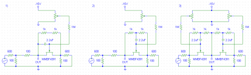
Of course, the simulator models are not ideal, but the basic effects can be well seemed. And, not need to simulate for to understand that the balanced schematic is as the divider with the identical impedances in both sides, and this means, that when the balance is done, then no harmonics voltage will be in the middle point.
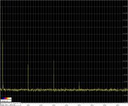
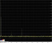
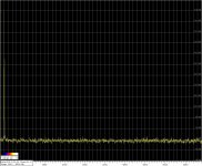
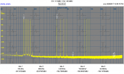
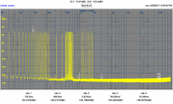
Here are the practical harmonic measurements of the different regulators with the FETs.
The 1kHz signal across the every FET (MMBF4391) s-d was app. 60mV rms.
1) Regulator without 1/2 s-d on the FET's gate.
2) Regulator with 1/2 s-d on the FET's gate.
3) Balanced regulator. FETs was matched for similar Vgs off. For to minimize the harmonics the small offset was needed.
Victor.
Attachments
![0017_09[1].png](https://www.diyaudio.com/community/data/attachments/572/572897-a6faa32c1298f4b48f343aedb40e682b.jpg "0017_09[1].png")
Victor, can you please add
withoutbalanced regulator
to your simulations? Thank you1/2 s-d on the FET's gate
Ever so slightly off track is the real need for an multi-tone/FFT system we can build ourselves.
capable of at least 10 tones before 5KHz and more would be a lot better.
Many more than this ---
View attachment 622852
Can be design that here?
THx-RNMarsh
Richard, did you get yourself a dScope?
Richard-
Like this? Its a triband spectral contamination file (loopback on the RTX analyzer at 192 KHz). 1 million point FFT, 10 averages.
Lots of tones gets really difficult if they are not to have harmonics or IM products on top of other tones. Another similar test would be white noise with notches. Again I'm not sure if you would learn something new. The underlying non-linearity would be the same. These IM tests do have the benefit of working in band limited systems.
This is a good test for drivers. Lots of coherent averages will unmask noises and other garbage you would otherwise miss.
Attachments
Dimitry, are you interested in the simulation results or the practical measurements? My last posted pictures was the PRACTICAL results measured on the table today.Victor, can you please add without to your simulations? Thank you
Probably simulator will show no harmonics in your case, but the practical balance will be very sharp and hardly done, because of the more higher overall distortions in every side of the balanced regulator without the 1/2 d-s on the gates.
Victor.
Richard-
Like this? Its a triband spectral contamination file (loopback on the RTX analyzer at 192 KHz). 1 million point FFT, 10 averages.
Lots of tones gets really difficult if they are not to have harmonics or IM products on top of other tones.
.
No. more tones throughout freq range.... like music.
No I didn't buy a dscope. Looking for cheap and fast way to get there. I just want to test my thoughts on something. Not long term investment and high cost.
-Richard
still waiting for multitone of decent electronics to show something new
we have many decent soundcard loopback multitones showing next to nothing - just noise baseline with 10s of tones tests
presumably with their stock op amps
for circuits without clearly visible THD I don't expect high number of multitones to show much new
although this mini-dsp plot does look like something's wrong:
http://www.diyaudio.com/forums/ever...-24-listening-test-opamps-11.html#post5113352 (just a few posts later there's a clean soundcard loopback plot)
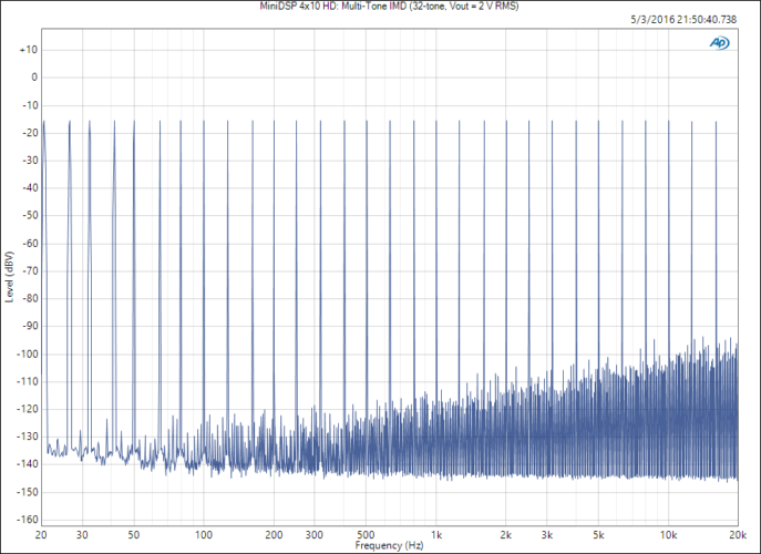
but I see more complete measurements that confirm my expectation - rising THD from 1 kHz, classic 1st order rise:
https://www.neurochrome.com/minidsp-4x10-hd/
clearly 2 tone IMD is powerful, there may be further resolution of some types of nonlinearities with 3 tone tests - but so far I haven't seen the value of high numbers of test tones
we have many decent soundcard loopback multitones showing next to nothing - just noise baseline with 10s of tones tests
presumably with their stock op amps
for circuits without clearly visible THD I don't expect high number of multitones to show much new
although this mini-dsp plot does look like something's wrong:
http://www.diyaudio.com/forums/ever...-24-listening-test-opamps-11.html#post5113352 (just a few posts later there's a clean soundcard loopback plot)
but I see more complete measurements that confirm my expectation - rising THD from 1 kHz, classic 1st order rise:
https://www.neurochrome.com/minidsp-4x10-hd/
An externally hosted image should be here but it was not working when we last tested it.
clearly 2 tone IMD is powerful, there may be further resolution of some types of nonlinearities with 3 tone tests - but so far I haven't seen the value of high numbers of test tones
Last edited:
Maybe this is closer? Its 60 tones all together. later I can add more HF tones but really nothing to see. It has a 100 dB active range operating as above with the actual level at approx -10 dBFS. The RTX is in the 10V out to 10V in range so the actual level is around 3V.
If you have a specific requirement for the tones let me know.
If you have a specific requirement for the tones let me know.
Attachments
No I didn't buy a dscope.
But the screen you posted in #6852 is from a dScope....?
Jan
- Home
- Design & Build
- Equipment & Tools
- Low-distortion Audio-range Oscillator