Three grades of BC327/337 are sold, binned by hfe: -16 is 100-250, -25 is 160-400, and -40 is 250-630. ... the -40 grade has a wider spread of values, so there will me more scatter of the individual devices in a typical build ....
I don't mind binning them myself. The lots of the -25's (100 of each) I bought didn't go up to 400 and there were big gaps in distribution of Hfe value in the PNPs, whereas the NPN's had Hfe's all squarely in the gap of the PNP Hfe distribution making for NO matched pairs at all), so I'll get some -40's for the next build (the boards you sent).
It wouldn't entice me. When someone gold-plates the shaft and the nut that holds the unit to the front panel, it tells you that their priorities are focused mostly in convincing stupid audiophiles to pay extra money for it.
That said, putting the attenuator in a metal can like that isn't a bad idea at all... I'd just want to see a full tear-down before considering an endorsement.
Edit: just found this. #facepalm
The thing is about the Elma switch is you can tell the money goes into the important bits like the cast metal housing, the detents and bearings, the silent make/break contacts, the high quality PCB ...
Last edited:
A fringe benefit of paying $160 for the Goldpoint is the luxury to completely ignore EIZZ entirely, and I suggest you don't let it take up any more of your time. It's just another sub-par Chinese-made part that must eventually disappoint, just like the switch on the Takman unit we both had previously.
You don't have to do anything, you can just use whichever parts falls out first from the antistatic bag. The trimmer resistor is designed to mop up residual statistical variation.
But if you want to measure hfe, what I suggest is you grade the BC337 so the parts you use are all within about 30 of each other, and the same for BC327. It doesn't matter if the ranges are different for the pnp and npn transistors.
Finally if you want to go "the full Stan"") you also check the Zener diode drops are similar between channels, and finally try to get Q1 and Q2 as close to a matched pair as possible.
you also check the Zener diode drops are similar between channels, and finally try to get Q1 and Q2 as close to a matched pair as possible.
While all these things have some potential performance benefit - I guess - the main achievement here is screening the parts to make sure they are all within close tolerance. If you are really, really unlucky a random selection of un-screened parts could land the required offset voltage outside of the trimmer's range. It's not the transistors that worry me so much as the Zeners, actually, as they seem to have a very wide spread.
But if you want to measure hfe, what I suggest is you grade the BC337 so the parts you use are all within about 30 of each other, and the same for BC327. It doesn't matter if the ranges are different for the pnp and npn transistors.
Finally if you want to go "the full Stan"
you also check the Zener diode drops are similar between channels, and finally try to get Q1 and Q2 as close to a matched pair as possible.While all these things have some potential performance benefit - I guess - the main achievement here is screening the parts to make sure they are all within close tolerance. If you are really, really unlucky a random selection of un-screened parts could land the required offset voltage outside of the trimmer's range. It's not the transistors that worry me so much as the Zeners, actually, as they seem to have a very wide spread.
Last edited:
Nice one rjmI borrowed the BD139,140 models Mike used in his LTSpice simulation. BD135,137,139 and BD136,138,140 are the same but for the voltage rating.
Changing the output transistor from BC337/327 to BD139/140 has no material influence on the simulation output that I could see.
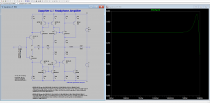
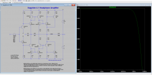
One of the more useful things you can do with the sim is compare open loop and closed loop distortion for different values of R2,R3(X). You can also remove R3(X) and look at the open loop gain and phase margin as a function of R2.

With minor changes it turn into nice power amp.
The thought has crossed my mind. That blog post needs to be edited again - knowing what I know now I would make the circuit closed loop, and there are some other things I need to fix up.
The hope is that at some point I will have collected enough data and experience from the Sapphire project that a power amp version naturally crystallizes out. Perhaps next year.
The hope is that at some point I will have collected enough data and experience from the Sapphire project that a power amp version naturally crystallizes out. Perhaps next year.
Last edited:
Richard, as you already know I assembled my 41m boards using 1k for R2A and R3X since that was the values listed for a earlier BOM.
It seems to work fine with those values, but I don't have a scope to verify if there are any issues with using those values or not.
So...what's the difference(s) between using 1k for both vs. using 2.2k, which are the values listed in the latest BOM?
Thanks.
It seems to work fine with those values, but I don't have a scope to verify if there are any issues with using those values or not.
So...what's the difference(s) between using 1k for both vs. using 2.2k, which are the values listed in the latest BOM?
Thanks.
1k-1k gives lower phase margin and less stability. While the simulated response shows a small amount of peaking, please note this is at high frequencies and easily damped out with the addition of 20 pF of input capacitance. I don't think it is worrisome or particularly relevant, but I changed the BOM to 2k to be on the safe side.
Attachments

Yes, closed loop all the way. Using laterals (k1058/j162) in the output gets you rid of thermal worries and using them in common source mode maximizes the output voltage swing (no Vgs loss). Also, degeneration resistors in current mirrors can be much lower value, etc... Anyway, nice future project... I would make the circuit closed loop, and there are some other things I need to fix up....
So, I am finished assembling my sapphire 4.1m.
I selected the transistors and the diodes as suggested by rjm above and had no trouble setting the output bias.
I used the parts listed in the BOM, and used R3 config with the default values for R2xx (should fit my AKG K701). I chose to use 1 transformer for the 2 boards and an Alps RK27 Pot.
As input capacitor I used a Wima MKP4-250 .47 uF, as my supplier does not have "audio-grade" components.
I listened to it for about 2 hours and I am very pleased.
First thing I noticed was the bass, which is more "present" than with most other Headphone Amps I had. But it's not exaggerated so it is not stressful to listen to music with a lot of bass.
In general you can hear many details in the music.
I have to listen some more to give some more impressions.
I am thinking about exchanging the input cap to something like a Mundorf cap. Has anyone experiences on how that affects the sound?
I use a Mundorf. I haven't compared to the Wima, but you can reasonably expect some improvement.
While the circuit will settle after a few days powered up, the coupling cap can take longer.
R3/R2 - so you mean you have the buffer open loop then? That's another tweak option, in addition to the coupling cap.
If I ask nicely can you post photos?
While the circuit will settle after a few days powered up, the coupling cap can take longer.
R3/R2 - so you mean you have the buffer open loop then? That's another tweak option, in addition to the coupling cap.
If I ask nicely can you post photos?
I am thinking which pot will be cost effective (and good sounding) choice,
- RK27 : No one recommend it...
- TKD 2CP-601 : I saw reviews with good result, but I am still not certain.
- DIY with Elma 24 pole switch : This could be best choice for p/p. costs approximately $120 depending on resistor selection.
- Goldpoint attenuator : $165 + $55 (shipping), it's more expensive than whole parts of Sapphire.
Anyone has other recommendation?
Or has anyone tried shunting pot?
Shunt Pot Volume Control for Better Sound and/or Gain Reduction - World-Designs-Forum
I think this is great alternative of shunt type stepped attenuator.
(or better in terms of pop-noise)
But I barely find information about that.
* 2 pcs * of 10K * D shape shaft * DACT Type 21 Stepped Attenuator Potentiometer | eBayAnyone has other recommendation?
- Home
- Amplifiers
- Headphone Systems
- RJM Audio Sapphire Desktop Headphone Amplifier