Certainly.
It was explained here by forum member ChocoHolic (entry #9).
Also, look at the 2092 datasheet, typical connection - they use 12V.
Oh, and I see, you do not ask why I made this, but how. I swapped the 15V Zeners for 12V Zeners.
I forgot to mention that I rated up the wattage of those.
Note that on the L15D there is a second (15V) zener diode that is not part of the original design, i.e. does not show up on the reference sheet they deliver (which is an excerpt from the original IRAUDAMP7s design).
-h
Last edited:
Note that on the L15D there is a second (15V) zener diode that is not part of the original design, i.e. does not show up on the reference sheet they deliver ;
Thanks a lot. I'll do that mod. What is the purpose of that extra zener? I didn't receive my L15's boards yet so I can not look for it.
The bottom bridge mosfet is easily turned on, being of n-channel type. 4.5 Volts will already turn them on hard according to the data sheet.
The upper half bridge mosfet is of n-channel type too and needs a charge pump to level shift voltages. The zener goes from pin 13 to 15.
Both zeners limit the voltage on the respective drive outputs.
12V appear more than enough.
The chip has built in protective zeners that limit at 20Volts, but apparently the higher the voltage on the driver the higher its dissipation.
At that high a switching frequency the mosfet gate charge takes its toll...
-helmut
Ricren,
I have seen this too, but I am not sure if this is real. In the vicinity of a radio transmitter all appears polluted.
Those residual contaminations are very hard to measure in my experience.
Maybe somebody here has suggestions.
I´ve put a zobel network onto the speakers too, on the other end of the cable.
This is what Bob Cordell recommends.
On the other hand, I do not see what harm it can do.
Let us know if you find a remedy.
-h
When you say if it's real what do you mean? The pict you see is the output of one of my LD20 modules, measured by me.
Very real, believe me.
All modules have the same leak. The designer of the board talked about it earlier on this thread, appears to be a choice. Other class D implementations (I have a few different class D amps.) do not have such a big leakage.
If I'd use it for a subwoofer, I would not care, but for mids or hi range, I wonder what happens when you use a supertweeter. If I find out, I'll report back.
I do not doubt your measurements, but I doubt mine.
When I had the modules on the bench supply, with improper wiring all over the place and a shunt resistor I saw some fuss on the signal.
I then doubted the reality thereof since I was fairly sure that even my ground lines were not clean.
I do not see that fuss on your signal. Those notches I don´t know about.
If there is any HF leakage, and I am sure there is, then (unless it were excessive) the speakers just would not respond to it I imagine.
I read in an article on measuring switch mode power amplfiers that all class-d amps that employ a similar method (i.e. a simple RC) to suppress the carrier on the output will exhibit some residual noise. They reference another article on Guidelines for Measuring Audio Power Amplifier Performance
where they write:
If HF were excessive, as in the case the inductor failed or the cap, then, yes then we would speak of excessive energy on the speaker that were like DC-the speaker receives a lot of energy but cannot move.
So I think we are relatively save.
-h
When I had the modules on the bench supply, with improper wiring all over the place and a shunt resistor I saw some fuss on the signal.
I then doubted the reality thereof since I was fairly sure that even my ground lines were not clean.
I do not see that fuss on your signal. Those notches I don´t know about.
If there is any HF leakage, and I am sure there is, then (unless it were excessive) the speakers just would not respond to it I imagine.
I read in an article on measuring switch mode power amplfiers that all class-d amps that employ a similar method (i.e. a simple RC) to suppress the carrier on the output will exhibit some residual noise. They reference another article on Guidelines for Measuring Audio Power Amplifier Performance
where they write:
In Maxim app. note 3977 they say:Class-D RC Low-Pass Filter
An RC filter is used to reduce the square-wave output when the analyzer inputs cannot process the pulse-width modulated class-D output waveform. This filter has little effect on the measurement accuracy because the cutoff frequency is set above the audio band. The high frequency of the square wave has negligible impact on measurement accuracy because it is well above the audible frequency range and the speaker cone cannot respond at such a fast rate.
Even if residual switching energy results in speaker movement, these frequencies are inaudible to the human ear and will not adversely affect the listening experience.
If HF were excessive, as in the case the inductor failed or the cap, then, yes then we would speak of excessive energy on the speaker that were like DC-the speaker receives a lot of energy but cannot move.
So I think we are relatively save.
-h
Last edited:
I do not see that fuss on your signal. Those notches I don´t know about.
-h
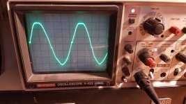
What you are seeing in the screen IS the leakage signal, a wave of around 400khz.
Oh I see.
We are talking about some volts of carrier here!
This of course is inacceptable. There must be something wrong with your output stage filter. Sure the coil and cap are intact?
But funny. If we were looking at the carrier here, the waveform would be a square wave. Your scope should be able to display this speed no problem.
I did not observe such things on my modules. Do you have a 10:1 or 100:1 probe?
-h
The osciloscope is in 0.5v/division, so you can see around 3v p/p carrier residue.
And it is not a square wave because is taken after the inductor/capacitor output filter where the carrier is already filtered.
Are you sure your modules do not have this carrier at the output? According to someone early in this same thread, this leaked carrier is "normal' with this design. I think.
And it is not a square wave because is taken after the inductor/capacitor output filter where the carrier is already filtered.
Are you sure your modules do not have this carrier at the output? According to someone early in this same thread, this leaked carrier is "normal' with this design. I think.
Ricren,
I investigated some more.
So your 3Vp-p align nicely with 1Vrms.
I can hear nothing detrimental on the tweeter. Sounds sweet and nice.
I have included a 100R/10nF (X-type) zobel down the very end too as Cordell recommends.
-h
I investigated some more.
source: Class-D Amplifiers(...) if our supply rails are +/-50V (enough for about 275W at 4 ohms), the residual ripple will have an amplitude of about 1Vrms. This ripple is, obviously inaudible, and 1V RMS will dissipate only around 200mW in a typical tweeter (not likely a problem, especially since the tweeters impedance will be a lot higher than 8 ohms at 300kHz). However, care must be taken as the speaker wires can become an antenna and affect other equipment. In fact, although a couple of volts RMS of ripple can seem low enough to run your speakers safely, EMI can be a concern, so the less carrier level you have, the better. For further rejection, higher order filters are used (...).
So your 3Vp-p align nicely with 1Vrms.
I can hear nothing detrimental on the tweeter. Sounds sweet and nice.
I have included a 100R/10nF (X-type) zobel down the very end too as Cordell recommends.
-h
Aquataur,
Yes, I was reading the same information, still I wonder about intermodulation effects of this carrier on the audible spectra.
Besides, I have other class D modules with a different design that not have this leak so I was wondering if this residue was ok.
Let's call it a day and move on, apparently this design is what it is. I'll use it for the woofer part of muy 3 way speakers for the time being.
I also found this: Switching Amplifier (Class D) Basics | Audioholics
Also read part 2 of this series. In that frequency range, other laws rule.
Yeah, let´s move on and listen to some music.
But as I said before, there is nothing to complain about the sonic quality for midrange and tweeters. Remarkable for that price.
And I like the repair-ability.
-h
Question 3: Will it radiate from my speaker cables?
Answer: Depends. Cables make good antennae inasmuch as their length is comparable to a quarter of the wavelength of the RF signal. A 350kHz carrier has a wavelength of 857 meters (2800ft.). A 5 meter speaker cable will not make an efficient antenna at this frequency. What this means is you're not going to get the FCC on your doorstep to complain about illicit transmissions in the AM band. This does not guarantee your own AM reception won't be compromised, but the neighbours' is OK.
Also read part 2 of this series. In that frequency range, other laws rule.
Yeah, let´s move on and listen to some music.
But as I said before, there is nothing to complain about the sonic quality for midrange and tweeters. Remarkable for that price.
And I like the repair-ability.
-h
I have a question for you. D20 is a good amplifier. But there is more powerful version, D25 version, about 250watts in 8 ohms. I do not know if 250 watts are effective or peak. But a seller, told me that it can run from 50volt to 80 volts without loss of power. I do not think I'm wrong. You have already tried amplifier D20, what is your optimum voltage for working with D25? How much current does it need? There is good smps to work with 2 D25 amplifiers?
thanks for your advice
thanks for your advice
I have a question for you. D20 is a good amplifier. But there is more powerful version, D25 version, about 250watts in 8 ohms. I do not know if 250 watts are effective or peak. But a seller, told me that it can run from 50volt to 80 volts without loss of power. I do not think I'm wrong. You have already tried amplifier D20, what is your optimum voltage for working with D25? How much current does it need? There is good smps to work with 2 D25 amplifiers?
*
*
*
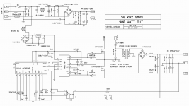
In your opinion, this smps 900watt + -70v is good for 2 boards?*
*
*
thanks for your advice
Attachments
I believe you are the most suitable person to ask a question. I have amplifier D25. I want to work with +/- 70v and load 8ohm. How many watts must be power supply smps?
There is math formula, to know how many watts need to work D25.
Sorry for this stupid question, but I have problems with dimensioning power supply
There is math formula, to know how many watts need to work D25.
Sorry for this stupid question, but I have problems with dimensioning power supply
I believe you are the most suitable person to ask a question.
Hi,
whom do you mean? Does not matter.
However I have to say something about that.
I use 5 modules L15D (á 150W sinus).
Now those numbers are to be viewed with a gain of salt. While it may be true that such a module can output the rated power, no real life signal is sinusoidal.
Bear in mind that real music is hugely dynamic and that power demand rises with the logarithm. It is known that class-D amps have a very bad overload behaviour. Such a device clips harshly, very much unlike, say, a tube amp. Its useful musical range may therefore be much lower than its rated power would suggest if you want to maintain a safety margin. It is thus ludicrous to cater for its rated power.
To monitor all that, I made some LED display moduls with a µC that monitors peak and average power. To my very astonishment (I had read this before but only seeing is believing...) the average living room loudness dwells well below one watt. At pretty loud volume (not comfortable for longer...) the (pretty inefficient) midranges go to 1W occasionally, the mono subwoofer too.
The tweeters usually don´t even light the 20mW lamp.
So much for power consumption. With the fairly efficient speakers of today, it is beyond me who needs so much power for a home system.
So back to the calculation.
The SMPS I chose (connexelectronic SMPS500R), a 500W rated power supply, can output 750W short term. God forbid I ever come near that.
There may be some cases such as dipoles or other power hungry systems.
Note: this all is for home use. If you go professional, or if you plan to cover large venues, you are going to need the power, but I have a feeling those Chinese modules are not fit for that.
Peak vs. rated power:
I am convinced those modules can output the power for a prolonged time.
The term peak usually applies to power supplies that can deliver a certain power for prolonged periods, but can apply peak power only for short periods, since their reservoir caps are excavated.
Also, there might have been some compromise made on the cooling of the main switching elements. The MOSFETs certainly are rated for that power.
For the PSU, don´t forget you have a system that is switched at an efficiency beyond 90% unlike a linear PSU that is lossy whereever you look at.
IMHO there is no reason to do some vast overrating, although a system at low duty always runs cooler than one that is close to the edge.
But keep in mind what you want this system to do.
Hope this helps you to make a decision.
-helmut
Last edited:
- Home
- Amplifiers
- Class D
- My design L20D IRS2092+IRFI4020H 200W8R