@natdberg
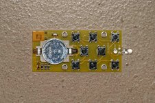
Just found out that there are several different batches of the VoICB circulating, depending when you ordered it and got it delivered from vicol-audio. Some buyers got a "green" PCB of seemingly different quality at least looking at the visible edges on those photographs. Can't say anything about differences in print quality though.
Mine (from the sale) is black and probably made by another board maker to different standards.
That might be the reason for our different views on this...
Anyone have an idea how to mount the VoICB board from Hans P. ?
It doesn't have mounting holes, thus chassis mounting seems not to be possible.
Because of those Hypex regulators "overlapping" on the left using dual row "very long" pinstrip headers (>30 mm, dual insulator) soldered in place of the 10 kOhm pot, as suggested elsewhere, might be possible, but will restrict access to those BPBP components directly underneath it, which I don't like. Note: The VoICB is then sitting "on top" of the BPBP. Otherwise one has to unsolder the VoICB before getting at them. Height might be problematic too...
Any 90° mounting done without those Hypex regulators getting into its way either ? This way the VoICB would sit right in front of the BPBP (vertical orientation) centered in front of the 10 K pot location.
What available hardware / connectors did you use for this ?
I tried a 90° dual row pinstrip header (pot location) for this already but it doesn't fit (to short).
Any pictures available if done ?
Look at this answer
http://www.diyaudio.com/forums/analog-line-level/291226-remote-control-bpbp-23.html#post5064945
Hans
OT
@NATDBERG
Sorry, if that has hurt your feelings, but it is what it is. I don't have any emotional connections with those sellers I buy from and their products, thus I look at the goods and their related quality rather unemotional but critical. And my expectations are certainly dictated by the price too, especially if it is supposed to be DIY...
/OT
I was getting the impression from your posts that it was you who was emotional about it, negative emotions, whilst I thought I was being more objective. Funny how differently people read things when it is only written and we are not talking face to face!
")
I took the Maya to be a well developed *commercial* product that was over-specified for our needs with the BPPBP as it comes with all sorts of control, power relays and sensors for integration with a larger project, IR remote learning etc etc and continuing firmware development. It has always been a commercial device slightly adapted for this DIY project.
Because of that I took a view of the price as a sophisticated product on it's own, not in comparison with other things that could control BPPBP volume. If I were to be doing that I would have settled for a motorised 10k linear pot from Alps and £5 remote board from ebay or simply copied Hans' original control scheme.
I saved a little bit by asking not to be supplied with the LCD so I could choose my own colour or even a vf display at a later date.
So, in my view, an objective view of the price would not compare it to other methods of controlling the BPPBP but it would be in comparison to another I2C controller with the same features for audio. Hence I think your comparison doesn't really apply and therefore it would be unfair to then complain it was too expensive.
The VoICB is ok to critise I guess - depends if there were any opportunities to discuss with Vicol about who they used or the quality/price. It was discussed when we were part of the GB and I'm pretty sure it was all about low cost.
Just a different take on the whole thing .
I finally finished my preamp yesterday. My final configuration is to use the board as supplied, with the correct size caps! I found a small 12v toroid "in stock" so I used that to power the board, and have used an ALPS linear motorised pot, but with 1k resistors at each end of the track to limit the gain/attenuation to about 16dB which suits my needs well. The motor is controlled by four relays, switched in pairs, using 433MHz RF remote control (basically two cheap relay boards from eBay) - the remote system is powered from a small SMPSU (£3.50 from eBay) with a tiny 12v to 5v converter (about £1) - so the remote volume is electrically independent from the audio circuit. The input selector switch isn't an on-off-on (as I didn't have one) but a SPDT works fine, except there is no mute. I only use one input anyway, and the switch is on the rear panel. Case and knob were from Audiophonics in France, though the case is the same as I get from Douk Audio on eBay, so it matches my TTPSU and my MDAC PSU.
So, how does it sound? Basically, it doesn't. It's completely silent and hum free in operation and makes no noise through the speakers even at power up/down.
Making a meaningful subjective comparison between having the preamp in circuit and running my DAC direct to my power amp is quite difficult, but in terms of overall "enjoyment" it seems to be absolutely fine, whereas every other preamp I've tried has added some degree of veiling to the sound, even some quite respectable passives, both switched attenuator and pot based (I have both). The additional gain means I can now play vinyl loud again, which is the main reason for building this. Very happy with the result!
burkm
Thanks for all the info on that relay board. Shame about the common ground - I didn't think of that.
Out of interest, have you been able to tell how the ladder is configured - ie. how many resistors are in-circuit at any particular setting? I guess you really need the cables to operate it and see what is going on
Hi ChrisPa,
I tried to order a 2nd relay board in the meantime, but the seller wants a 3 GBP surcharge for that 10 kOhm version now (18 => 21 GBP + 5 GBP shipment), arguing that he has to order the corresponding resistors now by himself because 50 kOhm is supposed to be "standard". Don't know about that, because the 1st (complete) set had been sold on ebay at the original price without any problems. Having the unpopulated board again (top) I will take some pictures of that layout. Might help then. But it is quite unfortunate to not have access to the schematics upfront. Should have thought about that beforhand and had ordered that "balanced" set right away... Sigh
Its unfortunate that the GNDs are combinded on that basic "stereo" relay board, because if not it would have been a simple and rather "cheap" alternative. Still like that overall design quite a lot and have been waiting for the missing cable set since to test at least the one channel I got before spending more on it...
Right now I am concentrating on the 2nd constellation using that Maya controller + VoICB from Hans P. (see corresponding thread from Hans P.). Just ordered the parts for that VoICB from digi-key because it has been a bit cheaper. Will get here mid-week probably.
Last edited:
@natdberg
My expectations are probably different than yours.
My "problem" is, that I really don't care if that relay board is been controlled using a bus like I2C (VoICB) or directly. I am just looking for a solution to replace the original pot within the BPBP with a relay / resistor ladder construct of decent quality and resolution using minimum effort on my side and - last but not least - remote control capabilities. In my understanding both products, Maya + VoICB and the Chinese made Zero Zone L168-45, I got right now are "professional" made. There are other solutions around as well like i.e the RelaiXed2 Passive volume controller by Jos van Eijndhoven at a price level comparable to that Maya controller combination and there are probably even more that I have missed...
If I find one at 1/2 the cost of that Maya control solution... fine. Don't forget those additional (balanced) inputs which come (almost) for "free" on that other volume controller, if needed, by chosing the balanced version of L168-45.
We will see which solution finally does work as expected and at what price, which I will prefer then...
My expectations are probably different than yours.
My "problem"
is, that I really don't care if that relay board is been controlled using a bus like I2C (VoICB) or directly. I am just looking for a solution to replace the original pot within the BPBP with a relay / resistor ladder construct of decent quality and resolution using minimum effort on my side and - last but not least - remote control capabilities. In my understanding both products, Maya + VoICB and the Chinese made Zero Zone L168-45, I got right now are "professional" made. There are other solutions around as well like i.e the RelaiXed2 Passive volume controller by Jos van Eijndhoven at a price level comparable to that Maya controller combination and there are probably even more that I have missed... If I find one at 1/2 the cost of that Maya control solution... fine
. Don't forget those additional (balanced) inputs which come (almost) for "free" on that other volume controller, if needed, by chosing the balanced version of L168-45. We will see which solution finally does work as expected and at what price, which I will prefer then...
Last edited:
Check what Hans did originally , I'm sure he made a controller that could easily be reconfigured for remote operation. All the VOlCB needs is a front end that can send i2c values to the board. A matter of knowing what to look for I guess, some kind of remote with receiver that outputs the correct i2c signal.
Definitely the Maya is a lot of money if you only want it for one of it's features! That makes it your choice to spend the money , fully aware of that, hence it's unfair to criticise the board or price, only fair to criticise your own choices if you were looking for low cost..
Definitely the Maya is a lot of money if you only want it for one of it's features! That makes it your choice to spend the money , fully aware of that, hence it's unfair to criticise the board or price, only fair to criticise your own choices if you were looking for low cost..
Last edited:
Why should I keep from questioning the quality of my VoICB PCB or should refrain from providing some suggestions of my own ? Its my opinion and as such as valid as everyone else writing on this forum / thread...
I spent the money and bought it together with the Maya controller, thus I have all the rights to do what I did, don't I ?
Don't get it
It's just some product, isn't it..
I spent the money and bought it together with the Maya controller, thus I have all the rights to do what I did, don't I ?
Don't get it
It's just some product, isn't it..
Last edited:
I can see you're right that you don't get it because I've not suggested you don't say any of that.
I was pointing out the futility of critising a product for being expensive when you are in full knowledge of paying for features you don't want.. kind of daft unless it's expression of regret.
Let's leave that there before we ruin a nice thread.
I was pointing out the futility of critising a product for being expensive when you are in full knowledge of paying for features you don't want.. kind of daft unless it's expression of regret.
Let's leave that there before we ruin a nice thread.
@ChrisPa
The missing (4) cables arrived (volume attenuator). Look neat and tidy, because they can't be inserted the wrong way. I probably will only need two of those for the whole setup.
Will separate the 4 input relay board from the attenuator board first by just cutting the traces at those predetermined positions to do some measurements on the attenuator afterwards.
Will report back about my findings...
This will take some time because I am working right now on testing and adjusting a counters timebase with my GPSDO. That needs time...
If everything works out as planned the 2nd channel attenuator / input board plus enclosure with conforming cutouts (for XLR, power, front display, encoders etc) etc. for mounting everything neatly will be ordered next (sum 76 GBP + VAT + ?). We will see...
If anyone knows gervenja, please get in touch with him.
He hasn't replied with the information and is refusing PMs. It looks like he only joins group buys and no recent posts so unless someone can get in touch, I'll remove him from the GB.
Gervenja, I did receive your PM, however you're still not accepting PMs and I cannot contact you!
Please copy/paste text from first post in this thread and email me - hypexpreampgb at xavbroadcast.co.uk
Thank you
Thanks.
I suppose it's worth asking:
you can't just break the common ground connection on the board you've already got so that it's separate for each channel, can you?
I would like to but can't. The ground plane is common to both channels and only have a single connection and trace an both sides (input/output) of the attenuator.
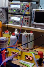
I started to do some measurements and tests on that "stereo" version I got.
Input resistance, which is supposed to be a "constant" 10kOhm, measured with some slight deviations over the complete range of 128 steps:
Max: 10.080 kOhm
Min: 9.957 kOhm
This is to be expected, because the resistor ladder consists of distinct values, which have to be matched to the steps.
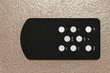
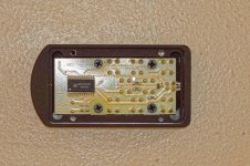
I opend up the IR-remote controller and inserted a battery (CR2032). Its really machined from a solid block of alumium incl. the buttons. Soldering (mostly SMT) was done by hand and OK, but the board hasn't been cleaned / washed thus some residue of solder flux was present, which I removed.
I connected the controller board (incl. relay board: attenuator and input) to my bench power supply (15.5VDC): power consumption is about 0.112 A. If all relays are active might be somewhat higher.T he stacked linear voltage regulators 12VD + 5VDC reached about 40°C (both) during continued operation.
I checked the functionality of all relays, attenuator and input board: OK.
The color of those large LEDs for input selection and attenuator steps is "red", which I did't like that much, but one can replace them as needed.
I checked the functionality of the IR-controller: input selection, volume attenuation, standby (pwr), mute, LED dimming (Disp, 3-5 steps) and setup (memory). Everything worked as expected. These functions are present (mostly) on the front panel too. Two encoders of the push and rotate type variety are used for that.
Next thing will be checking the resistance values of all steps and the corresponding attenuation of a signal I am going to feed into the attenuators input. Because it is a "simple" passive direct coupled resistor network I probably will use just DC...
Attachments
Last edited:
Continued...
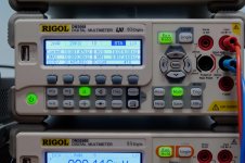
I measured attenuation for 1 channel (128 steps) step by step and arrived at the follwing values:
Input voltage: +8.24 dbU = 2.00022 V
Attenuation range: theoretical 64 db, measured 63.73 db
A slight deviation and non-relevant (?) step to step variations in attenuation are visible compared to the theoretical 64 db (128 * 0.5 db).
I listed the individual values for each step in the attached .TXT file.
Attachments
Is there any gain? Is the maximum output equal to the input?Continued...
I measured attenuation for 1 channel (128 steps) step by step and arrived at the follwing values:
Input voltage: +8.24 dbU = 2.00022 V
Attenuation range: theoretical 64 db, measured 63.73 db
A slight deviation and non-relevant (?) step to step variations in attenuation are visible compared to the theoretical 64 db (128 * 0.5 db).
I listed the individual values for each step in the attached .TXT file.
What do you mean by "gain" with respect to that tested passive resistor based ladder attenuator ? Probably a misunderstanding because I haven't been as clear in my description as I wanted to...
Max attenuation available is around 64db (step 1), minimum attenuation (step 128) is 0 db. Some precaution has to be taken into consideration for that "max gain" problem in combination with the BPBP.
I just measured the attenuation of each of the available 128 steps and the maximum plus minimum attenuation achievable to see how it performs in this respect using a 2V signal. And I measured the max / min input resistance for all 128 steps (s. txt file).
That attenuator network is supposed to be inserted in place of the 10 kOhm linear pot of one of my BPBPs in the near future.
Next thing to do: I will have to take a look if any modifications are needed for that replacement. For a complete setup a 2nd 10 kOhm relay board is needed because of that common GND (L/R stereo version) issue, as stated before.
This configuration is available as standard in the balanced version whilst 10 kOhm input resistance is an available option..
The whole set to be fitted into that case mentioned is then:
- BPBP
- 128 steps volume controller incl. IR remote control
- Power supply +/-15 VDC (and may be another +15 VDC ?) depending upon overal power consumption and voltage needs.
- ...some might consider that 4 input relay board additionally which is included with the volume controller already
I ordered the 2nd relay board plus case already after I finished testing the 1st one.
Last edited:
- Status
- This old topic is closed. If you want to reopen this topic, contact a moderator using the "Report Post" button.
- Home
- Group Buys
- Bruno Putzeys Balanced Preamp - Group Buy Part 3