Very good! time to make some new measurements (but I have said this since late NovemberI finally got a 40KG6 tube to test here. (ie PL509) This is a Raytheon tube, made in Japan. Looks to be well made and measures well. Even has the RCA dark emitter heater.
All are curve traced at 50 mA/div Vert. and 50V/div Horiz.
1) normal g1 drive, -1.5V steps on g1, 78V on g2, top curve is 0V on g1
2) g2 drive, +5.5V steps on g2, g1 at 0V, bottom curve is 0V on g2
3) triode mode, -7.5V steps on g1, top curve is 0V on g1
4) Twin/Crazy drive (g2 and g1 with resistors), +3.5 V steps on g2, Rg2g1 = 888 Ohm, Rg1k = 2770 Ohm, bottom curve is 0V on g2 (and g1)
 so no one will believe me )
Some business take all time (including my new purchase, the locky-z transistor tracer***) but with this new data I will find some time to take new measurements. Easy now since I have purchased some russian Magnoval sockets and arrived last week.
I will experiment this values in some different PL509 brands (I have Matsushitas, Philips, RSD, Ultron and Sylvania)
***good to have a transistor tracer and make some peace of mind about device curve linearity and then tube don't look too bad, after all
Last edited:
Another odd thing about this tube is it does not have a evacuation stem seal. (not even the bottom) An advanced manufacturing process apparently.
This is common with top-capped European Magnoval tubes. They were evacuated and sealed by the top where the wire comes out.
Best regards!
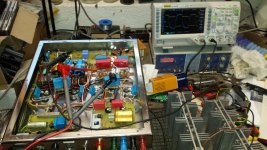
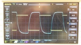
This week I had both my Circlotron monoblocks, built in 2001, on the workbench again for an overhaul. I replaced the worn-out PL519s and did some modifications in the NFB in order to increase stability on 8 ohms loads. As the 4 ohms terminal is grounded, with '0' at one side and '8' and '16' on the other, while '0' and '16' provided NFB to the symmetrical driver, there were huge oscillations if a load was connected to '0' and '8' by wires loger than 1 metre. Now this symmetric NFB comes from the OT's outer terminals, i.e. the PLs' cathodes. Output power is slightly more than 100 watts.
Some pictures. We see a 10 kHz square wave, right before clipping:
Some pictures. We see a 10 kHz square wave, right before clipping:
Attachments
Last edited:
I suspected as much. I had noticed a long thin glass bead on the plate wire within the tube. Pre-formed (pre-tinned? pre-glassed?) for sealing apparently.
You don't need it. Just weld the connecting wire to the plate (or cathode at dampers) and stick it's short end into the evacuation tube, then evacuate the envelope and melt the tube.
Best regards!
Likely not.
I can curve trace the tubes in triode mode at high voltages, but that would only find immediate breakdown problems. While the real issue is extended time usage with real watts dissipation.
The small gap across the mica insulator between grid1 and grid2 is where high insulation stress occurs. Lengthy surface ion bombardment can cause a creeping insulation failure path across that small gap. Eventually causing run-away or even flash-over.
There is also the issue of grid 2 warping from over temp (even glowing!). Some in circuit measurements of grid 2 current (and Vg2) could likely predict that failure at least.
As George (Tubelab) has noted, my curve tracing of some sweep tubes in triode mode (like 6LW6) are highly over-optimistic for long term use.
One could maybe try to collect observations from experience with various tubes in amplifiers.
..
Last edited:
One might try measuring ion current (from residual gas) in a tube to predict premature failure problems in triode mode. Just put negative 300V or so on the plate with the cathode heated, and measure the uAmps of plate ion current. Probably still requires electron current flow to a positive grid 2 to ionize the residual gas. Tricky to avoid melting grid2.
Maybe easier to just measure negative V grid 1 current, with grid2 and the plate at the usual positive V's.
This would not particularly select out the non-getterable gas (like Argon) ion flow however, unless the tube had been operated hot normally for some time before the measurement to insure recently active gettering. There would still be the issue of released gas, from occasional over-heating of the tube interior elements, possibly releasing more un-getterable ions.
Last edited:
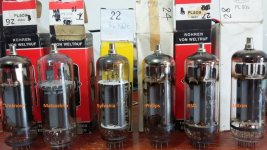
Some TV Sweep tube pics, with the 40KG6/PL519 for comparison.
From bottom to top: 21LG6A, 6HJ5, 35LR6, 26LX6, 40KG6, 36LW6
Hi smokingamp,
do you know any datasheet of this huge 21LG6A? Frank Philipses' solely refers to one of the 6LG6A, which sadly isn't available.
Best regards!
"huge 21LG6A?"
6LG6 and 21LG6 are the same except for heater V. You may have missed that the tubes in the pic were listed from bottom to top. In which case the "huge tube" would be the 6LW6/26LW6/36LW6 at the TOP. GE specifically made the big diameter (1.75 inch) version of that tube. I think most of the other vendor's versions were the usual 1.5 inch diameter. But I do see big ones on Ebay that don't have the GE logo, could be re-labels?
the 21/6LG6 data:
https://frank.pocnet.net/sheets/123/6/6LG6.pdf
26LW6 on Ebay:
26LW6 GE VINTAGE TUBE - NOS IN BOX | eBay
Only direct LW6 data I see on Frank's site is this, not much:
https://frank.pocnet.net/sheets/135/3/36LW6.pdf
The GE handbook has a line data listing for it.
However, the M-2057 is the exact same tube, but with a different heater and pin-out, with the full curves:
https://frank.pocnet.net/sheets/084/m/M2057.pdf
Some testing:
6LW6 Sweep Tube | Tubelab
...
Last edited:
I have never seen any mention of frame grids for the 6KG6/PL509/519 series. The Matsushita tube does not have them. Frame grids usually mean at least 2X the gm versus normal grids. Like the 8417 tube versus 6L6GC. Generally, frame grids also mean un-aligned grids (due to extremely close grid wire spacing and tiny wires). However, nothing would prevent a manufacturer from winding a normally pitched set of grids on a frame and aligning them still.
If you look through any holes present in the plates, and can see the grid 1 wires, usual frame grids have such tiny and closely spaced wires that they can barely be seen individually, more of a continuous reflective sheen. The grid 1 and grid 2 wires in the Matsushita tube are pitch spaced about 0.75 mm I would guess. (and wire aligned between grid 1 and grid 2)
If you look through any holes present in the plates, and can see the grid 1 wires, usual frame grids have such tiny and closely spaced wires that they can barely be seen individually, more of a continuous reflective sheen. The grid 1 and grid 2 wires in the Matsushita tube are pitch spaced about 0.75 mm I would guess. (and wire aligned between grid 1 and grid 2)
Last edited:
Even cats love magnificent TV tubes, with local feedback around them...
https://www.facebook.com/Wavebourn/videos/1376336922424605/
https://www.facebook.com/Wavebourn/videos/1376336922424605/
Very charming, but in my experience cats really love biting through cables!
Did you design an adequate driver for crazy drive? No free lunch!
Anatoliy, I'm happy to use mosfet followers, (even as outputs); I'm not allergic to sand. Also, I don't actually need much power since I use very efficient speakers but I find the idea of twin drive fascinating. Anyway, I have a long break from giving lessons to students so I'm hoping for some good progress with this. The sweep tubes that are easily available to me, PL36 and 6P36S have not been characterised for crazy drive so I think it best to try to screen drive them first. I realise that triode connected or Schaded 6P36S would probably be hard to improve upon but I feel like trying it out anyway.
I am much in admiration of your large and varied production recently!
I am much in admiration of your large and varied production recently!
but in my experience cats really love biting through cables!
And puppies.
jeff
- Home
- Amplifiers
- Tubes / Valves
- Those Magnificent Television Tubes