Output, does that mean there is an audio signal voltage plus a bias voltage?
If there is a variable signal voltage then the 10uF MLCC ceramic will change capacitance and that can lead to distortions of the output signal.
Better to use at least an MKT for signal coupling duty.
1uF would feed 100k of Zin, or go to 3u3F for a 30k of Zin.
If there is a variable signal voltage then the 10uF MLCC ceramic will change capacitance and that can lead to distortions of the output signal.
Better to use at least an MKT for signal coupling duty.
1uF would feed 100k of Zin, or go to 3u3F for a 30k of Zin.
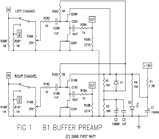
The output at the cap should probably be close to several mV DC as I tried to match the Idss of the two JFETs, the blocking cap is just there for insurance - although I could probe it and know for sure. This hybrid cap system with a small 10uF 50v MLCC and a 1uF (to 3.3uF) film cap is how I have all of my amplifier input DC blocking caps where a 10uF electrolytic is called for. A 10uF film cap is huge and would be about same size as my entire PCB for the B1.
Would a 10uF 63v electrolytic cap be better than the 10uF 50v MLCC?
I basically followed this with a few changes (2.2mF vs 10mF caps for C1 & C2, 6.8k 2w for R2 & R3, P100 is 50k vs 25k, no R1 used, 2x 4.7k for R4, and of course the 10uF MLCC + 1uF 230v film vs 10uF film for C101 ):
Would a 10uF 63v electrolytic cap be better than the 10uF 50v MLCC?
I basically followed this with a few changes (2.2mF vs 10mF caps for C1 & C2, 6.8k 2w for R2 & R3, P100 is 50k vs 25k, no R1 used, 2x 4.7k for R4, and of course the 10uF MLCC + 1uF 230v film vs 10uF film for C101 ):
Last edited:
C201 & 101 are @ ~9Vdc of bias + the signal voltage.
That does not suit a Hi K ceramic.
Use a polar electrolytic that is at least 20times the size needed to pass 20Hz or use an MKT that is 10times the size needed to pass 20Hz. If size and cost were no obstacle, then use FKP.
You can decide what value you need from F-3dB = 1 / {2PiRC}
Rearranged to C >= 10 / {2piRF-3dB} for MKT, or twice as big for electro.
BTW,
the leakage depleting resistors R205 & 105 can be much larger. Try 2M2
When this is combined with a similar value at the receiver and the 100k of Zin, you end up with an effective load of 1k + 2m2||2m2||100k = 1k+91.7 = ~92k7
This suits a 1uF MKT that fits a 7mm tall by 5mm by 6mm footprint with 5.08mm pin pitch that costs pennies.
Last edited:
BTW,
the leakage depleting resistors R205 & 105 can be much larger. Try 2M2
When this is combined with a similar value at the receiver and the 100k of Zin, you end up with an effective load of 1k + 2m2||2m2||100k = 1k+91.7 = ~92k7
This suits a 1uF MKT that fits a 7mm tall by 5mm by 6mm footprint with 5.08mm pin pitch that costs pennies.
That's an interesting thought, but the input impedance to my amp is 22k, so would that mean I need at least 5.6uF?
That's the design by Juma for the BJT headamp. I think one of the goals of the B1 was to be able to drive low impedance loads. So maybe the whole "keep it compact" notion may be tough with need for film caps of 10uF size. Although with the MLCC caps, by ear, does not sound to be distorted - and I am quite sensitive to distortion especially noticeable with piano or certain female vocals. One of these days, I will get a proper amp distortion measuring rig.
I think one thing I would like to point out is that the B1 preamp is wonderfully simple to make and sounds fantastic. Don't let the lack of a real PCB hold you back on this one. As we can all see, it's an easy P2P job on a basic 4x6 veroboard. Had I used a bigger one with more real estate, it would certainly be even easier to make.
Juma actually suggested use of J310
Last edited:
Yes, the B1 is so simple. I used the Dennis Feucht version with the two source resistors, to build a tiny 4pole S&K filter for a bass only speaker.
Power came from the power amp PSU with an RCRC to get the voltage down from 50Vdc to 20Vdc. That whole Circuit Board was about 35mm by 25mm.
Power came from the power amp PSU with an RCRC to get the voltage down from 50Vdc to 20Vdc. That whole Circuit Board was about 35mm by 25mm.
Attachments
I did not use passive filters.
I used two S&K 2pole filters to give a 4pole filter that is half of an LR4.
There is a Thread discussing this from a year, or two back.
The opamp you refer to in a unity gain S&K filter is wired for no gain. Rather a waste of an opamp !
I thought it was better to use a unity gain Follower rather than a unity gain opamp.
")
I just replaced the 10uF 630v capacitors in my Pass B1 preamp. I was using a pair of Clarity ESA's and just swapped in a pair of Obbligato Gold's, same value. Right off the bat with no break in there was a noticeable difference. The sound stage became more 3D or holographic. The overall sound is a bit softer and less forward with more air and transparency. Bass is toned down slightly which is a good thing because the preamp has way too much bass. Treble has more air and detail. It is also a bit more prominent. The sound stage is much wider and taller. They definitely are a bit on the warm side like the Clarity ESA's. I don't have the caps soldered in yet. They are connected using alligator clips. I won't make a final determination as to whether I will keep them in the B1 or put them in the Pass balanced preamp that I am building (Bride of Son of Zen) until I have about 50 hours on them. The ESA's have a more focused sound. The caps are paired with Mundorf M-Caps, 1uF 630v.
Any one know how to tone down the bass of this preamp? Resistors are shinkoh Tantalums, Audio Note Tantalums, Riken Carbon at the outputs and Z foil TX instruments at the input. Volume pot is Blue Alps 50K.
Any one know how to tone down the bass of this preamp? Resistors are shinkoh Tantalums, Audio Note Tantalums, Riken Carbon at the outputs and Z foil TX instruments at the input. Volume pot is Blue Alps 50K.
The B1 Buffer does not have any EQ inside.Any one know how to tone down the bass of this preamp? Resistors are shinkoh Tantalums, Audio Note Tantalums, Riken Carbon at the outputs and Z foil TX instruments at the input. Volume pot is Blue Alps 50K.
It does not exaggerate the bass and cannot be used to attenuate the bass.
But you can use the High Pass DC blocking capacitor as a 6dB/octave filter.
Swap out the two existing capacitors with a pair that are half the value.
If that is not enough then try ¼ value
This will roll off the extreme bass.
But I supect what you are hearing is the bass hump in your speaker.
Many speakers have a bass hump in the frequency response. This is deliberately designed in to allow the box to be manufactured smaller than optimum. This can be exaggerated when there is some extra source impedance from the amplifier and cables.
Try moving the speaker away from all boundaries. Does that make any difference?
Try moving the speaker to where you are normally seated and walk around the room to find the peaks and nulls in the room. Where you find a null, swap your head/ears with the speaker and return to your seat. You will now hear that nulled output from your listening seat. You can use this swapping speaker and ears technique to find a good location for your speakers that gives the most balanced bass reponse.
new builder... possibly old questions
Dear mates
I know I am almost sure I'm gonna making points already discussed... pardon me, I tried to go through the immense amount of posts about the B1 but it was very difficult to find what I need.
I hope somebody can point me to the relevant 3D/posts in this forum about:
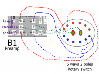
1. the pcb sold on PassDiy are for 2 inputs only, I need more than 2 inputs (at least 4), there is any simple way to adapt to this?
2. there is any consensus on wich power supply to use? I have this available at hands
Placid HD Bipolar Power Supply
do you think is ok for the B1?
3. there is any consensus on relavent parts to use for optimal performance (caps, resistors etc)
Best Wishes
Pierre
Dear mates
I know I am almost sure I'm gonna making points already discussed... pardon me, I tried to go through the immense amount of posts about the B1 but it was very difficult to find what I need.
I hope somebody can point me to the relevant 3D/posts in this forum about:
1. the pcb sold on PassDiy are for 2 inputs only, I need more than 2 inputs (at least 4), there is any simple way to adapt to this?
2. there is any consensus on wich power supply to use? I have this available at hands
Placid HD Bipolar Power Supply
do you think is ok for the B1?
3. there is any consensus on relavent parts to use for optimal performance (caps, resistors etc)
Best Wishes
Pierre
Just use ordinary commercial quality components. Don't use fakes from Ebay and others.
The B1 does not use a Bipolar power supply.
Download the B1 .pdf and read it thoroughly. Follow up with questions after that read through.
The Mesmerize (DCB1) had 6 inputs selected by signal quality relays.
The B1 does not use a Bipolar power supply.
Download the B1 .pdf and read it thoroughly. Follow up with questions after that read through.
The Mesmerize (DCB1) had 6 inputs selected by signal quality relays.
2. there is any consensus on wich power supply to use? I have this available at hands
Placid HD Bipolar Power Supply
do you think is ok for the B1?
Pierre
You need a monopolar 18V power supply, I had nice sounding results with the Sigma 11 The σ11 regulated power supply
But any 18V wall power supply will be enough.
Best
Any one know how to tone down the bass of this preamp? Resistors are shinkoh Tantalums, Audio Note Tantalums, Riken Carbon at the outputs and Z foil TX instruments at the input. Volume pot is Blue Alps 50K.
Odd - I don't notice any overemphasis in the bass of my B1. I am guessing that AndrewT is correct that it is a speaker design and/or placement issue.
- Home
- Amplifiers
- Pass Labs
- B1 Buffer Preamp