Hi all
Why don`t you try a resistor from point A to ground (1K-10K)?
This will make the impedance "seen" by the transformer more linear.
Maybe you have a bit of dc bias on the primary side of the transformer? This will make the core characteristics highly non-linear.
Just a thougt:Is the OP-amp well in its limits of voltage supply? Too low voltage? Decoupling cap from V+ to V-?
Regards
Arne
Ah, change R2 for 100 kOhm. It will be a working high input impedance buffer to see what the output signal is.
If there is still distortion one can check other things.
Ok, that's a good test. Will try that.
In principle it should work, therefore a few questions:
What power supply is used for the opamp and are the supply pins properly decoupled with 100nF.
I see only a signal line going from left to right but no signal ground.
There should be a firm connection between the trafo earth and the earth on R2.
Be careful in mixing earth and signal ground, they are not the same.
Hans
Sorry for confusing you about protective earth ans signal ground. Signal ground is a solid wire.
Hi all
Why don`t you try a resistor from point A to ground (1K-10K)?
This will make the impedance "seen" by the transformer more linear.
Maybe you have a bit of dc bias on the primary side of the transformer? This will make the core characteristics highly non-linear.
Just a thougt:Is the OP-amp well in its limits of voltage supply? Too low voltage? Decoupling cap from V+ to V-?
Regards
Arne
Ok, the DDDAC output is capable of driving transformers by design. There are many DDDACs out there that work fine with this, and mine also did before I moved to the TVC and Sallen Key filter.
The data I've shown in my first post was taken with the TVC at its lowest volume setting. To test the transformer drive / load I set the TVC to 12' clock setting and attenuated the test signal from the DAC chips in the software to get the same signal amplitude at the TVC output. The result is that the distortion at the filter output is gone!
This tells me this:
- The setup does work in principle.
- GND is ok (or at least not all wrong). And PSU decoupling on the opamps is ok (yes, the small caps are there).
- The distortion depends on the TVC setting.
I really think the complex impedances are playing nasty tricks on the opamp. Any ideas how to control this?
And why on earth does inserting a buffer / voltage follower between the TVC and the filter not solve the problem?
Hi all
Why don`t you try a resistor from point A to ground (1K-10K)?
This will make the impedance "seen" by the transformer more linear.
Already tried that (see post 10).
Maybe you have a bit of dc bias on the primary side of the transformer? This will make the core characteristics highly non-linear.
My DVM says the DC across the primary is 0.000 V. If the distortion was due to saturating the transformer or similar, the output signal of the transformer would already show the distortion.
Just a thougt:Is the OP-amp well in its limits of voltage supply? Too low voltage? Decoupling cap from V+ to V-?
Voltage supply is +/- 15 VDC. Decoupling capacitors next the the opamp are 47uF electrolytic and a small ceramic.
Ah, change R2 for 100 kOhm. It will be a working high input impedance buffer to see what the output signal is.
If there is still distortion one can check other things. The OP wants a highpass filter there, not a buffer (except for this test)
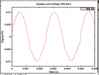
Ok, I removed R1, bridged C2, changed R2 to 70 kOhm and left C1 as is (100 nF). This left me with a voltage follower with coupling capacitor at the input (100 nF) and a 70 kOhm resistor that provides GND reference at the pos. input of the opamp (RC constant is 7 ms).
Result: output signal is still distorted, but looks different than before (see attachment). Yes, the input signal to the opamp / voltage follower is clean (confirmed this).
So the distortion is happening in the opamp. But why?
(just to repeat from post 25: the distortion goes away at higher volume settings of the TVC, so it must be a combination of the TVC setting and the inner workings of the opamp).
Attachments
the distortion goes away at higher volume settings of the TVC, .
smells like some crossover distortion of op-amp.
I have no idea about opamps. Is this something that opamps tend to do?could the opamp be reacting to seeing a high input impedance?
I have no idea about opamps. Is this something that opamps tend to do?
No of course not.
But you still haven't responded to:
1) power suppy
2) decoupling
3) what type of 100nF caps are used
Hans
Did you test your circuit while you assembled it? I put a few parts in at a time, then I do basic resistance checks. Op amps go in last. I look at the schematic and say "if I measure between these two points then the resistance should be x" and then I measure. It's easier than just assembling the whole thing and then trying to figure out why it doesn't work.
I've had circuits that have all the right DC voltages but distort the signal. It's usually either conductive traces (trash) on the board, or else a cold solder joint.
Just yesterday I powered a circuit up for testing. One channel was oscillating. It was a really simple circuit, and the DC voltages were correct (although didn't match as closely as they usually do). I started checking the little 0.1 uF bypass caps for looseness and cold solder joint when I realized that I had not allowed for a ground trace to these capacitors. I slapped a jumper wire on the bottom of the board, and problem solved.
My point is that there's many stupid reasons why a simple circuit won't work correctly.
1) power suppy
It's a shunt regulated balanced +/- 15VDC. I also tried a regulated lab/bench supply, didn't make a difference.
2) decoupling
Here's a picture of the filter electronics as it looked a while ago. You can see the electrolytics on the "main" board. The smaller "daughter" boards wrapped in heat shrink are the opamp filters, which also have electrolytics and ceramic decoupling capacitors on their own (I removed the heat shink in the meantime for testing purposes). The single "daughter" board one on the left is the high pass filter in question.
3) what type of 100nF caps are used
I'd guess they are polyesters.
Did you test your circuit while you assembled it?
...
My point is that there's many stupid reasons why a simple circuit won't work correctly.
I didn't assemble everything on my own. I got the DAC and the xovers pre-assembled (I was too lazy to do it on my own). The DAC has worked well for many years now. The xover is new, and I had the problem from the start. I basically disassembled and rebuilt the whole thing and tested it in between. Couldn't isolate the problem other than the opamp chips (signal going in is fine, signal coming out is distorted).
I didn't assemble everything on my own. I got the DAC and the xovers pre-assembled (I was too lazy to do it on my own). The DAC has worked well for many years now. The xover is new, and I had the problem from the start. I basically disassembled and rebuilt the whole thing and tested it in between. Couldn't isolate the problem other than the opamp chips (signal going in is fine, signal coming out is distorted).
I can see a 14 pin IC connected to the output of your filter. What IC is this and did you look at the filter output signal wthout this IC.
Obviously the signal ground is on the other side of the PCB. Is this a ground plane or what ?
Maybe you can also make a picture of the backside.
Hans
I can see a 14 pin IC connected to the output of your filter. What IC is this and did you look at the filter output signal wthout this IC.
It's a quad opamp. Two of those are used as output buffers (1 x high pass, 1 x low pass, 2 x unused). I tested the output of the high pass before and after this buffer. I also tested with the output buffer removed. No difference.
Obviously the signal ground is on the other side of the PCB. Is this a ground plane or what ?
Maybe you can also make a picture of the backside.
Will send a picture once I get some workshop time.
Ok, I removed R1, bridged C2, changed R2 to 70 kOhm and left C1 as is (100 nF). This left me with a voltage follower with coupling capacitor at the input (100 nF) and a 70 kOhm resistor that provides GND reference at the pos. input of the opamp (RC constant is 7 ms).
Result: output signal is still distorted, but looks different than before (see attachment). Yes, the input signal to the opamp / voltage follower is clean (confirmed this).
So the distortion is happening in the opamp. But why?
(just to repeat from post 25: the distortion goes away at higher volume settings of the TVC, so it must be a combination of the TVC setting and the inner workings of the opamp).
OK, that was a good test. Distortion is less. Now do the same and leave out any input cap. So short C1 and C2 (DC coupled yes). Only do this when using OP275 (JFET input opamp).
OK, that was a good test. Distortion is less. Now do the same and leave out any input cap. So short C1 and C2 (DC coupled yes). Only do this when using OP275 (JFET input opamp).
I already did this. Result was the same as with the capacitor.
I already did this. Result was the same as with the capacitor.
Will it be possible to connect a sinewave oscillator to the input.
When the problems persist, the cause concentrates on the small pcb with the filter.
Hans
- Status
- This old topic is closed. If you want to reopen this topic, contact a moderator using the "Report Post" button.
- Home
- Source & Line
- Analog Line Level
- Crazy distortion problem with transformer and active filter (opamp / Sallen Key)