NFB falls as frequency rises.Hi Valery
I drive the OPA alone only loop using voltage generator driving the top of the voltage spreader. I adjust the offset of the generator to get the output as close to 0V as possible. Then I AC couple to 2ohm load with a high value cap to run the FFT.
My idea is just looking at the distortion created only by the OPS with the bias enhancement shown in this thread. I consistently get worst distortion than when I remove the bias compensation.
I actually simulated your circuit as it really look interesting and it make sense. But I got higher distortion in the FFT when I have the bias compensation circuit in than when I just disconnect D1 and D4 in your schematic( D2 and D3 in my simulation). I play with different voltage across Q5 and Q6 (Q17 and Q18) with no luck.
What is the reason I should simulate with the whole circuit including the IPS and VAS? I worry that the feedback gain mask the distortion of the OPS alone. That's why I run OPS alone without any feedback to look at the full distortion.
Thanks
Crossover distortion is a higher frequency effect.
The result is that NFB substantially attenuates the lower half of the crossover distortion products and slightly attenuates the upper half of the distortion products.
It's these (less attenuated) HF distortion products that we seem to perceive as "bad sounding".
Now look at a ClassAB stage that has some form of crossover reduction system. Does it create crossover products that have a similar frequency spectrum as a conventional ClassAB with optimal bias?
If the crossover reduction system produces more LF artefacts and produces less HF artefacts, then when tested alone you may find it appears to have worse distortion.
Now put that stage inside a global NFB loop and the higher level of LF artefacts could be better attenuated and the final result is a lower distorion AND "nicer sounding" because it started with fewer HF artefacts.
NFB falls as frequency rises.
Crossover distortion is a higher frequency effect.
The result is that NFB substantially attenuates the lower half of the crossover distortion products and slightly attenuates the upper half of the distortion products.
It's these (less attenuated) HF distortion products that we seem to perceive as "bad sounding".
Now look at a ClassAB stage that has some form of crossover reduction system. Does it create crossover products that have a similar frequency spectrum as a conventional ClassAB with optimal bias?
If the crossover reduction system produces more LF artefacts and produces less HF artefacts, then when tested alone you may find it appears to have worse distortion.
Now put that stage inside a global NFB loop and the higher level of LF artefacts could be better attenuated and the final result is a lower distorion AND "nicer sounding" because it started with fewer HF artefacts.
Makes a lot of sense. I observe a sort of the same thing, simulating the OPS with feed-forward error correction - the profile and level of low-order harmonics is roughly the same (just very slightly lower), but all the higher-order "garbage" is suppressed significantly. This is, what I believe, makes it sounding better. Our prototype is still in the building stage, so I will report back later on this.
Hi Audiocrase, that's right.Hi Valery
Thanks for your response. I am very interested in your circuit. Do you mean in your last post, you actually only simulate the OPS alone and drive the input of the OPS with 100ohm resistor and got the FFT plot?
Your result is a lot better than what I got in LTSpice simulation. It must be something I did wrong with my simulation. Can you tell me how you set the voltages on the few places I shown in my attachment? Particularly the voltage across D2 and D3. I experimented quite a bit with my simulation, the attachment show my final voltage on both the voltage spreaders. I don't know whether it is optimal or not.
Thanks
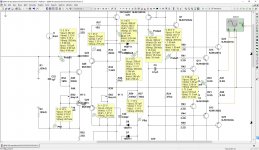
Attached picture demonstrates the voltages and currents in the key points of the circuit (no input signal, DC offset is close to zero).
Cheers,
Valery
Attachments
Fascinating, Valery, you are keeping all the outputs at a controlled, minimal current - absolute textbook zero switching. Very impressive, this deserves very close scrutiny.
Maybe you should never publish the schematic, no?
Hugh
I think this one was published last Christmas. http://www.diyaudio.com/forums/soli...e-old-ideas-1970s-ips-ops-35.html#post4554894
I can confirm it sounds great, but haven't been able to make proper distiortion measurements yet.
Member
Joined 2009
Paid Member
I wonder if keeping the schematic secret provides any real business advantage any more ?
If you are a commercial branded manufacturer you sell based on strength of advertising, distribution, reputation, quality manufacturing and good sound. And attention to operations to keep profitable.
Who can rip you off if you publish your schematic ? - the DIY'er who wants a cheap amp off eBay isn't going to buy your product anyway. Most of the chinese ebay rip-offs are not very profitable but if you think one of them has a chance you can claim copyright infringement and have eBay kick them off.
We can already build amplifiers with negligible distortion - the problem is upstream of the amps these days. Crappy source and/or crapy recoding quality. I wonder if we're better off with worse amplifiers to mask all the junk. It seems that home theatre amps are designed this way sometimes.
But I do like the non-switching approach for use of CFP outputs where their strength is high linearity and negligible beta droop but they don't always like to turn on and off. The circlophone by Elvee is a good example although I've never heard it.
Last edited:
Fascinating, Valery, you are keeping all the outputs at a controlled, minimal current - absolute textbook zero switching. Very impressive, this deserves very close scrutiny.
Maybe you should never publish the schematic, no?
Hugh
Thank you Hugh. It's been published and experienced at least 3 layout re-designs for now. All layouts work well - the main advantage of the latest one, designed by Jeff is possibility to use interchangeable snap-on front-ends (NS OPS is a "carrier" board in this case).
The right implementation of this thing is rather tricky - thermal compensation of the clamping circuit is a serious engineering task - the mechanism is rather precise. Also, the clamping mechanism requires careful tuning for the best performance.
The whole thing, from the simulated schematic to mass-production-type-of design took about a year of research, prototyping, testing and amendment iterations.
NFB falls as frequency rises.
Crossover distortion is a higher frequency effect.
The result is that NFB substantially attenuates the lower half of the crossover distortion products and slightly attenuates the upper half of the distortion products.
It's these (less attenuated) HF distortion products that we seem to perceive as "bad sounding".
Now look at a ClassAB stage that has some form of crossover reduction system. Does it create crossover products that have a similar frequency spectrum as a conventional ClassAB with optimal bias?
If the crossover reduction system produces more LF artefacts and produces less HF artefacts, then when tested alone you may find it appears to have worse distortion.
Now put that stage inside a global NFB loop and the higher level of LF artefacts could be better attenuated and the final result is a lower distorion AND "nicer sounding" because it started with fewer HF artefacts.
Hi Andrew
Makes a lot of sense
Hi Valery
I drive the OPA alone only loop using voltage generator driving the top of the voltage spreader. I adjust the offset of the generator to get the output as close to 0V as possible. Then I AC couple to 2ohm load with a high value cap to run the FFT.
My idea is just looking at the distortion created only by the OPS with the bias enhancement shown in this thread. I consistently get worst distortion than when I remove the bias compensation.
I actually simulated your circuit as it really look interesting and it make sense. But I got higher distortion in the FFT when I have the bias compensation circuit in than when I just disconnect D1 and D4 in your schematic( D2 and D3 in my simulation). I play with different voltage across Q5 and Q6 (Q17 and Q18) with no luck.
What is the reason I should simulate with the whole circuit including the IPS and VAS? I worry that the feedback gain mask the distortion of the OPS alone. That's why I run OPS alone without any feedback to look at the full distortion.
Thanks
Here is the way I do it. I measure or simulate the output stage distortion in-situ, with the complete amplifier in place. This takes a lot of guesswork out of the process.
Whenever I build and amplifier, I center-tap the driver emitter bias resistor that connects the emitters of the top and bottom drivers. This node is basically the input to the output stage. With feedback in place, total amplifier distortion is much lower than the open-loop distortion of the output stage up to frequencies well above 20kHz. If you place a distortion analyzer at this center-tapped driver node, you will see the distortion that is needed to drive the output stage to make a low-distortion output.
This is just input-referred distortion of the output stage. Its absolute polarity is inverted, but this does not matter. This approach to evaluating output stage distortion is valid as long as the amplifier output distortion is at least, say, 10 times less than the open-loop distortion of the output stage.
Cheers,
Bob
Bob - a good one, as long as we don't consider the pre-drivers being part of the OPS.
When I ran initial tests on the non-switching prototype, I have split the NFB resistor into 2 x double-value ones and connected them to the positive and negative shoulders of push-pull VAS output (just on both sides of bias spreader) - works well if NFB netwok's impedance is relatively high.
The drawback of the approach - we slightly load the VAS, decreasing its output impedance at the same time (improving its driving capabilities with regards to OPS). However, the whole OPS, including the pre-drivers, is running clean outside the global loop, allowing open loop measurements and valid comparison with other OPS topology options.
Cheers,
Valery
Let's talk about what is the goal here. What is the best realistic distortion for a very high quality amp( with or without any of these)? Is 100db down on the 2nd and 3rd harmonics good enough on a complete amp? Or you think they can do better?
Also, at what output signal level? It's tricky, crossover distortion is worst at low signal level, so what signal level is the base to qualify these crossover cancellation design? Going for max signal before clipping is really hiding the problem of crossover distortion.
Also, at what output signal level? It's tricky, crossover distortion is worst at low signal level, so what signal level is the base to qualify these crossover cancellation design? Going for max signal before clipping is really hiding the problem of crossover distortion.
Let's talk about what is the goal here. What is the best realistic distortion for a very high quality amp( with or without any of these)? Is 100db down on the 2nd and 3rd harmonics good enough on a complete amp? Or you think they can do better?
Also, at what output signal level? It's tricky, crossover distortion is worst at low signal level, so what signal level is the base to qualify these crossover cancellation design? Going for max signal before clipping is really hiding the problem of crossover distortion.
OK. My view on this.
Distortion level is not the only thong we're looking at. The profile is very important.
Distortion in crossover region creates a lot of high-order components, not correlated with the input signal. Single tone sine wave is a very easy thing to handle. Music is a much more complex combination of sine waves with different frequencies and amplitudes. Each of them creates this switching-related "garbage" - it soms up, some components are cancel-out, but some others increase. Plus, in many cases, we experience inter-modulation, producing even more "new" stuff, in the output signal, comparing to the input one.
-100db on a single tone sine wave is good, but what happens if we see look at 2-3 tones or MLS (maximum length sequences, about, say, a 100 components within the audio range) type of signals? Is it still -100db?
Inter-modulation is a very important point. Depending on the mechanism causing it, there may be the 1-st order products (f1+ f2, f1 - f2) or some secondary ones, like f1 - (f2-f1) and f2 + (f2-f1), dominating at the output signal. Two signals, say, f1=14KHz and f2=15KHz, can generate 1KHz component (very well-heard), plus 13KHz and 16KHz ones, that will interact with something else, creating even more new stuff.
Transient inter-modulation (TIM) is even worth, as it creates even more components, even less related to the input signal.
Subjectively, all this things are percieved as a "transistor" kind of sounding.
When I measure the prototype on a test bench, here is a minimum set of measurements I normally go through:
- THD at 1, 10 and 20 KHz, at 20, 6.5 and 3V RMS at 8 ohm load; in case of hi-end design with a good power supply and a lot of output current capabilities, it makes sense to run these measirements at 8, 4 and 2 ohm load;
- IMD 14+15KHz, -6db level each, at the same RMS and load levels, as above;
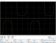
- Square wave response at 20Vpp, 8 ohm load, at 1, 10, 20, 50 and sometimes 100 KHz - tells a lot about transients handling, stability, frequency and phase response; rise/fall time, slew rate can be measured at the fast fronts;
- MLS handling - in case of bad handling, noise floor noticeably raises, showing a lot of "unwanted" new components in the output signal;
- Clipping behaviour at 1KHz and 20KHz. Less artifacts - better quality.
Cheers,
Valery
Thanks Valery for the detail explanation.
I just wonder why nobody talk about two tone test much. All just 1KHz and 20KHz.
Do you test TIM?
Thanks
I'm arranging appropriate setup for measuring TIM the right way - combination of a sine wave and a low-pass filtered square wave in certain mix is required. It's a very good test, proving the overall quality level of the amplifier.
One more thing - forgot to mention above - I normally build an automated Bode plot (amplitude and phase responses vs frequency, up to 1MHz, on one diagram). You can see both high-frequency rollover on the amplitude curve, and phase shift at 20KHz and above at the phase curve. I normally target the phase shift at 20KHz being less than -4 degrees. Things like the bandwidth, phase response and slew rate are pretty much inter-related, so this 20KHz phase shift value pretty much confirms the overall quality, if it's low enough.
You are giving all the good ideas away!!! Lucky for us.
Thanks
but is nonswitching OPS useless outside of GNFB loop?
Is it possible to use it as just OPS?
How?
Hi Pawel,
Why would it be useless outside the GNFB loop? I tested it this way and it works very well.
What do you mean by "just OPS"? Unity gain buffer?
- Status
- This old topic is closed. If you want to reopen this topic, contact a moderator using the "Report Post" button.
- Home
- Amplifiers
- Solid State
- New Class A, Super-A, Non-Switching : need a revival ?