What passive notch does not need gain correction (second picture 2nd and 3rd harmonics are read directly off of screen). I might have missed one of Samuel's musings.
Hi Scott,
If I'm really wanting to use a passive notch, I just manually correct the dB values for the harmonics where there is a significant error. Not a big deal, but doesn't result in a nice plot untouched.
Cheers,
Bob
Hi Scott, David,
No, I was unaware of those posts. Had I seen them, the changes would have been made already. Scott, if you see red, maybe post a picture of it along with the number of lamps in the string.
I used some in a custom CD filter / oscillator I made for doing a bunch of different CD player brands. It made semi-similar units a breeze to set up. Since I did a lot of CD product, the project paid off. Yes, those oscillators were overkill for the job at hand, but they were simple with above average performance. It even has a DB connector for the various harnesses for each CD player type.") It's been years since I used it last, but it has good memories attached to it. The box also had a setting for an external oscillator, so it was pretty close to future proofed. It even has an RF amplifier and output for the eye pattern.
It's been years since I used it last, but it has good memories attached to it. The box also had a setting for an external oscillator, so it was pretty close to future proofed. It even has an RF amplifier and output for the eye pattern.
-Chris
No, I was unaware of those posts. Had I seen them, the changes would have been made already. Scott, if you see red, maybe post a picture of it along with the number of lamps in the string.
I used some in a custom CD filter / oscillator I made for doing a bunch of different CD player brands. It made semi-similar units a breeze to set up. Since I did a lot of CD product, the project paid off. Yes, those oscillators were overkill for the job at hand, but they were simple with above average performance. It even has a DB connector for the various harnesses for each CD player type.
It's been years since I used it last, but it has good memories attached to it. The box also had a setting for an external oscillator, so it was pretty close to future proofed. It even has an RF amplifier and output for the eye pattern.-Chris
Hi Scott,
If I'm really wanting to use a passive notch, I just manually correct the dB values for the harmonics where there is a significant error. Not a big deal, but doesn't result in a nice plot untouched.
Cheers,
Bob
That's why I asked, if corrected for the second only by scaling everything, fine. I've build a few of these things that were like standing a pencil on its point which is actually a good analogy.
Scott, if you see red, maybe post a picture of it along with the number of lamps in the string.
-Chris
Seems to be a standard C7 base incandescent.
SVO UI
Hi Guys,
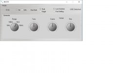
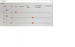
I made changes to my UI for the SVO.
The User controls on the original UI where a bit clunky in all respects.
I switched from rotary knob controls to slider controls. I'm still in the process of learning how to write my own controls so I don't have to depend on free offerings off the net.
I've added some functionality to the SVO which is included in the UI. I'm not quite ready to present performance data on these new functions but it's coming.
I've included a zip file of the UI. Please download it and give it a try. It won't do much without the hardware attached but you can still comment on the look and feel.
I no longer have an XP machine. I don't know that it will run on every platform.
It is written and compiled in C# for .NET on a win 10 machine.
I think the slider controls will work better on a touch screen as well.
Additionally, one person I send the old UI to for test had problem with graphical compression.Everything looked squished. I hoping this doesn't happen with the new controls.
A couple of pics of the old and new UI.
Cheers,
Hi Guys,
I made changes to my UI for the SVO.
The User controls on the original UI where a bit clunky in all respects.
I switched from rotary knob controls to slider controls. I'm still in the process of learning how to write my own controls so I don't have to depend on free offerings off the net.
I've added some functionality to the SVO which is included in the UI. I'm not quite ready to present performance data on these new functions but it's coming.
I've included a zip file of the UI. Please download it and give it a try. It won't do much without the hardware attached but you can still comment on the look and feel.
I no longer have an XP machine. I don't know that it will run on every platform.
It is written and compiled in C# for .NET on a win 10 machine.
I think the slider controls will work better on a touch screen as well.
Additionally, one person I send the old UI to for test had problem with graphical compression.Everything looked squished. I hoping this doesn't happen with the new controls.
A couple of pics of the old and new UI.
Cheers,
Attachments
http://www.diyaudio.com/forums/equi...on-audio-range-oscillator-55.html#post3497666
I know it was from a long time ago, but has this ever been built ?
Such elegant circuit, would be a shame not to ......
Patrick
.
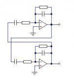
Yes. I am also thinking about this. Why no make generator absolutely simmetrical, when both inverters are similar like output stage now?
(AGC not shown)
I know it was from a long time ago, but has this ever been built ?
Such elegant circuit, would be a shame not to ......
Patrick
.
Attachments
Hi Guys,
I made changes to my UI for the SVO.
The User controls on the original UI where a bit clunky in all respects.
I switched from rotary knob controls to slider controls. I'm still in the process of learning how to write my own controls so I don't have to depend on free offerings off the net.
I've added some functionality to the SVO which is included in the UI. I'm not quite ready to present performance data on these new functions but it's coming.
A couple of pics of the old and new UI.
Cheers,
This is really nice..... cant wait to get my very own unit. The software GUI looks nice and straight forward for the user. Much appreciated.
THx-RNMarsh
http://www.diyaudio.com/forums/equi...mps and looked at performance?? THx-RNMarsh
This is really nice..... cant wait to get my very own unit. The software GUI looks nice and straight forward for the user. Much appreciated.
THx-RNMarsh
I tried it on touch screen. It seems the knob are bit to small. It Works though.
Maybe I'll do a second skin with bigger knobs for Touch screen selected in the menu.
This is really nice..... cant wait to get my very own unit. The software GUI looks nice and straight forward for the user. Much appreciated.
THx-RNMarsh
Richard if you have a change download the zip file. The executable is in the zip.
Click on the mode menu strip and you'll see the other options. There is more than what's visible on the pic.
using the touch screen would be very useful
THx-RNMarsh
OK I'll do a second skin with bigger knobs. Touch screen mode.
On my touch screen the sliders work OK.
However I would prefer direct entry. One of the aspects of the Boonton is the synthesizer accuracy of the oscillator. It has a tuning/disciplining loop tied back to the master TCXO clock and its tuneable to 5 digit accuracy. That plus the direct entry of output with a .1% accuracy gets its performance close to that of a real calibrator. With a micro it should not be too hard to do.
However I would prefer direct entry. One of the aspects of the Boonton is the synthesizer accuracy of the oscillator. It has a tuning/disciplining loop tied back to the master TCXO clock and its tuneable to 5 digit accuracy. That plus the direct entry of output with a .1% accuracy gets its performance close to that of a real calibrator. With a micro it should not be too hard to do.
On my touch screen the sliders work OK.
However I would prefer direct entry. One of the aspects of the Boonton is the synthesizer accuracy of the oscillator. It has a tuning/disciplining loop tied back to the master TCXO clock and its tuneable to 5 digit accuracy. That plus the direct entry of output with a .1% accuracy gets its performance close to that of a real calibrator. With a micro it should not be too hard to do.
Yes you've mentioned this before. It would be nice, very covenant.
But later on down the road as I have to R&D all that. The day job makes all this stuff really slow moving.
I have an alternative to this for the time being which allows for the tight tuning you're after.
I'll present this a bit later in the next two weeks or so.
light bulbs vs JFETs for oscillator AGC
In the long-ago past, I've owned one or two osillators that used bulbs for the oscillator agc. One was an EICO 377. When in college, I built a switched-frequency bridged-T oscillator using a thermistor for the agc element. It worked fine, but back then I did not have really good instrumentation for measuring THD.
After I graduated with my BS, I leaned of JFETs and their use as voltage-controlled resistors. Shortly thereafter I discovered how HP used a distortion-reduction approach with JFETs as the AGC element in their oscillators (they fed back half the signal at the drain to the gate). Since then I've only built oscillators with JFETs.
However, I do wonder if the old Tungsten lamp approach was actually superior in some regards. I must admit I've never done an apples-apples comparison. One variable that must be kept the same for a fair comparison is settling time and distortion at low frequencies, like 20Hz.
Cheers,
Bob
Well my SVO can settle at 20Hz to 95% in 2 seconds. But distortion at 20Hz is hard to measure because the harmonics collide with the power supply hum. Can we make 18Hz.
Well my SVO can settle at 20Hz to 95% in 2 seconds. But distortion at 20Hz is hard to measure because the harmonics collide with the power supply hum. Can we make 18Hz.
I recommend measuring at a frequency somewhere between 20 and 25Hz depending on your line frequency, and using a spectrum analyzer with pretty narrow bandwidth to look at the distortion output of your THD analyzer. It definitely takes care and patience to measure very low levels of such distortion in the presence of line and line harmonic frequencies.
This can also be a challenge in measuring power amplifiers. We usually talk about 1kHz THD and 20kHz THD, but one should definitely not ignore 20Hz or 50Hz (or thereabouts) THD in a power amplifier.
Cheers,
Bob
One variable that must be kept the same for a fair comparison is settling time and distortion at low frequencies, like 20Hz.
Cheers,
Bob
That's a problem the thermal time constant starts to overlap the frequency and you start to lose. BTW Bob I've given my for real retirement notice effective this holiday shutdown period. A perfect 42.
Hi Bob,
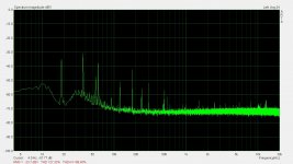
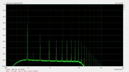
Here is the SVO at 18Hz 2.5Vrms measured on the Shibasoku 725D
The fist pic is in normal mode. The range is 0.001% (-100dB)
0dB on the ARTA scale is -100dB since the monitor output of the 725D is 1Vrms FS.
The meter is reading 9% of FS. So 9% of 0.001%. This calculates to -120.9 dbV THD+N.
To get past all the PS hum I switched the analyzer to analysis. In this mode the 725D suppresses the noise using synchronous averaging. This make it possible to measure the THD. In analysis mode the Shibasoku shows the first 10 harmonics. The fundamental is not visible
With all scaling the same. The meter is reading 3% of 0.001% which calculates to -130dBV
THD.
Attachments
- Home
- Design & Build
- Equipment & Tools
- Low-distortion Audio-range Oscillator