schematics and gerber files were available on Glen's new web site - not there any more 
schematics and gerber files were available on Glen's new web site - not there any more
He might help out if you email him directly. IIRC it was quite an undertaking not unlike some of the SVO's discussed here.
Where can I find out more about this?
THx-RNMarsh
Wayback machine: https://web.archive.org/web/20130128164157/http://www.users.on.net/~glenk/thd/thd.htm
However you would need an exceptionally good filter to get useful results. Its how the RE CLT1 and CLT10 get the -170 dB residuals. But that uses a 10W amp to get about 1W of drive. They use complex filters with Ferrite cup cores the size of footballs to get there.
J Curl used a cap across the output of the generator which can get you a 6 dB reduction in the 2nd harmonic etc. but in practice its never so simple.
J Curl used a cap across the output of the generator which can get you a 6 dB reduction in the 2nd harmonic etc. but in practice its never so simple.
Hi Richard,
I can't see how it couldn't. By definition you are reducing the amplitude of the harmonics, so a low pass would even be sufficient (unless low freq. noise is a problem).
-Chris
We talked about it for distortion measurmenets but no one tried it yet. Worth a try and see what we get for result.

THx-RNMarsh
Last edited:
Has anyone tried a narrow BP filter on an osc output to see if that reduces the osc/generator distortion?
It might make things worse. Remember that a high Q resonance
increases filter-internal voltages / currents substantially.
That is like using a crystal filter to remove phase noise from a crystal oscillator's output.
The filter can add its own phase noise.
I have been thinking about 5 crystal notches above and below a 10 MHz carrier
frequency. They could remove sideband power, but not be in resonance to the
carrier frequency, and at levels that would kill an xtal in resonance.
I even have made a board for that, but with my current pace it will take years to test it.
In your case, having notches at the harmonics seems more promising
than bp filtering the fundamental.
regards, Gerhard
Last edited:
IIRC the input amplitude has to be reduced to about 30mV or less depending on where the Q is for each frequency. At high frequency above 10kHz a controller is damping at all times.
This due to the Q enhancement effect.
It wouldn't take much to clip the filter.
The required damping is frequency dependent and is different, by a slight amount, for each adjacent frequency. This amount varies a lot over a wide frequency range.
The filter requires a controller like or the same as an oscillator if it is to operate at a high Q.
The difference being that the controller operates in damping only and not positive feedback.
If the Q is brought down to make it work then the effect is lost.
Hi Gerhard,
I have read about that before, I forget where. The application was the same (and so is my interest) in reducing noise in a lab 10 MHz reference oscillator and distribution amplifier.
I have maxed out the channels in my HP 5087A, and I want to build a larger one that isolates the output common connections. I'm currently working on a couple GPS receivers and OXCO oscillators. I'm interested in where you get to with your idea. I did consider the same filter with a crystal idea you just mentioned, but rejected it for the same reasons you did. Also, amplitude variations may be possible as temperature causes high Q filters to drift (back to an oven then?). More trouble than it's worth, and a simple LC filter can reduce the harmonics and noise away from the 10MHz signal, but no help for phase noise close in.
-Chris
It seems power supply noise would contribute to phase noise in an oscillator (more or less, depending on the circuit). A good parallel regulator, as I've seen elsewhere on diyaudio, could help. I've been following this thread off and on, but don't recall a lot of attention having been paid to the power supply.
I have read about that before, I forget where. The application was the same (and so is my interest) in reducing noise in a lab 10 MHz reference oscillator and distribution amplifier.
I have maxed out the channels in my HP 5087A, and I want to build a larger one that isolates the output common connections. I'm currently working on a couple GPS receivers and OXCO oscillators. I'm interested in where you get to with your idea. I did consider the same filter with a crystal idea you just mentioned, but rejected it for the same reasons you did. Also, amplitude variations may be possible as temperature causes high Q filters to drift (back to an oven then?). More trouble than it's worth, and a simple LC filter can reduce the harmonics and noise away from the 10MHz signal, but no help for phase noise close in.
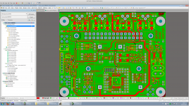
Maybe on the time nuts list. The filter is pretty low now on the priority list. Instead I have made a board that can carry a HP10811, Morion MV89 or MTI-260 crystal oven and phase lock it to an external reference. There is also a 1pps generator, optional frequency doubler / harmonic killer and output amplifier. I'd like to power-combine 2**n oscillators to average away their phase noise. I have bought at least 20 MTI-260 oscillators on ebay, packaged as HP/Lucent gps-less standby units and also got 20 of my boards
I'm also working on a IF3602-based successor to my 220pV/sqrt Hz preamplifier because I'm not so happy with its behaviour in the 1/f range. I want to use it as a ring mixer post amp to soup up my 89411A for cross corr. phase noise measurements to get independent of the E5052 at work, at least for some fixed frequencies.
I also see the problems with the phase noise filtering, but if one produces the oscillators, only 10% of the crystals have top phase noise performance. The other 90% are collecting dust. So the filtering could be a nearly free way to recycle them.
regards, Gerhard
Attachments
Hi benb,
Absolutely! Kill the noise source best you can before distancing yourself from it locally. Even batteries are noisy in their own way, no free lunch there.
Hi Gerhard,
That's a really nice board, and a good idea. I don't want to knock this thread off it's rails, we can take this to email, or you could begin a thread on your implementation and ideas. A lab frequency reference is a very useful thing, and I don't see it discussed much. I'm pretty sure there are other members that could contribute useful things to your project.
As for time nuts, certainly possible. That's another valuable reference source. I've learned a lot from the good folks on that list, and the references they are involved in are pretty darned good. Certainly better than the average hobbyist might need, but the basic idea is a solid one. Even a non-disciplined oven oscillator run into a few instruments would help with the digital devices we are starting to use. Right now, the idea would be a bench full of DVMs all calibrated to a different volt. Just trying to draw a parallel for people who haven't thought along those lines before.
-Chris
Building a low-distortion audio oscillator
Folks,
I am atttempting to build a wide-range ultra-low distortion oscillator along these basic lines
http://cds.linear.com/docs/en/article/ubm_edn_20110811%2018Bit%20ADCs%20Ad%20Free.pdf
or
http://www.janascard.cz/PDF/An%20ultra%20low%20distortion%20oscillator%20with%20THD%20below%20-140%20dB.pdf
It seems like a set of good C/2C capacitors are necessary and I've chosen ones based on a) on hand (I have lots of them) b) low D, c) reputation--polypropylene or polystyrene. The recent article in Linear Audio from Groner/Wurcer recommends C0G as well.
Is D (dissipation) in any way indicative of quality for the capacitors needed for these types of oscillators? If not, is there some simple test I can use short of having the Groner/Wurcer test fixture?
I'm trying to get five decades, 2.5-200hz, 250-2K...25k-200K. I've provisionally settled on caps in 3.3/6.6uf, .33/.66uf...range
I have access to a 0.005% distortion signal source (non-quadrature), a Keithley 2015, an Extech LCR meter, a frequency counter and a scope....
Thanks for any suggestions,
Randy
Last edited:
Those are both good projects but converting them to wide range will prove challenging. They have both been discussed in this thread (almost Audio Oscillator 101 combined with the best available info on ultra low distortion oscillators) but its a big thread with lots to read and absorb. There are at least two efforts that are really state of the art you should find and study before starting anything. It will save you from a number of dead ends.
Here's an inexpensive fixed frequency (1kHz) oscillator which can be adjusted to -105dB THD.
Assembled Low Distortion Audio Range Oscillator 1KHz Sine Wave Signal Generators
Assembled Low Distortion Audio Range Oscillator 1KHz Sine Wave Signal Generators
Here's an inexpensive fixed frequency (1kHz) oscillator which can be adjusted to -105dB THD.
Assembled Low Distortion Audio Range Oscillator 1KHz Sine Wave Signal Generators
This is not a bad little state variable oscillator for $11, and, being built with through-hole components, can be modified without much difficulty. Not sure about the quality of the tuning capacitors, but they can be changed. Also, it probably would not be difficult using some off-board components to at least get multiple switched spot frequencies. Replacing the 5532 devices with updated devices, like LM4562 or OPA2134 might also yield improved performance. This would also make a good starter design for those who might want to experiment with active or passive twin T notch filters to try to see the distortion.
Also, using 2 or 3 of these with a good op amp summer, a decent twin-tone CCIF 19+20kHz or triple-beat MIM source could be made.
Cheers,
Bob
- Home
- Design & Build
- Equipment & Tools
- Low-distortion Audio-range Oscillator