Hi Waly. See attached.
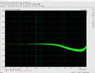
I haven't seen the schematic, but something is fishy here. If the open input noise is -160dB (at LF), it means that the input impedance (creating that noise at LF) is about 6500 ohm (10nV/rtHz).
If so, how would you expect to measure large resistors noise? This 6k impedance will voltage divide any noise coming from external sources (like a 470k resistor).
I understood the preamp input impedance design spec to be >100kR at 1kHz.
As noted above, I think my dabbling with a 470k resistor was flawed/ill thought out. I was worried that my regulator PSRR test setup (ripple rail driver->voltage regulator circuit "DUT"->preamp->Juli@ XTe sound card and ARTA) was somehow masking a 20dB per octave decline in my voltage regulator DUT's PSRR. I tested a 1K resistor, 10K and then 470K - seeking higher and higher noise levels. (As you will see from the spectrum analyser graphics posted in the thread discussing the regulator circuit, the general measured noise floor of the regulator is about -144dBV at 1kHz.) The results of the 470K resistor showed a circa 20dB decline in frequency response from around the exact same frequency that I would have expected a circa 20dB decline in PSRR of the regulator under test. I then jumped to conclusions...before then conducting a test using my signal generator (with voltage divider at its output/input to preamp) to deliver steps of frequencies into the pre-amp (post 157 above).
If so, how would you expect to measure large resistors noise?
As noted above, I think my dabbling with a 470k resistor was flawed/ill thought out. I was worried that my regulator PSRR test setup (ripple rail driver->voltage regulator circuit "DUT"->preamp->Juli@ XTe sound card and ARTA) was somehow masking a 20dB per octave decline in my voltage regulator DUT's PSRR. I tested a 1K resistor, 10K and then 470K - seeking higher and higher noise levels. (As you will see from the spectrum analyser graphics posted in the thread discussing the regulator circuit, the general measured noise floor of the regulator is about -144dBV at 1kHz.) The results of the 470K resistor showed a circa 20dB decline in frequency response from around the exact same frequency that I would have expected a circa 20dB decline in PSRR of the regulator under test. I then jumped to conclusions...before then conducting a test using my signal generator (with voltage divider at its output/input to preamp) to deliver steps of frequencies into the pre-amp (post 157 above).
Last edited:
I understood the preamp input impedance design spec to be >100kR at 1kHz.
As noted above, I think my dabbling with a 470k resistor was flawed/ill thought out. I was worried that my regulator PSRR test setup (ripple rail driver->voltage regulator circuit "DUT"->preamp->Juli@ XTe sound card and ARTA) was somehow masking a 20dB per octave decline in my voltage regulator DUT's PSRR. I tested a 1K resistor, 10K and then 470K - seeking higher and higher noise levels. (As you will see from the spectrum analyser graphics posted in the thread discussing the regulator circuit, the general measured noise floor of the regulator is about -144dBV at 1kHz.) The results of the 470K resistor showed a circa 20dB decline in frequency response from around the exact same frequency that I would have expected a circa 20dB decline in PSRR of the regulator under test. I then jumped to conclusions...before then conducting a test using my signal generator (with voltage divider at its output/input to preamp) to deliver steps of frequencies into the pre-amp (post 157 above).
Forget for a moment about the frequency rolloff and consider only the LF noise at 1KHz or so.
Once again, I haven't seen the schematic, but your open input noise measurement says that the preamp input impedance is as low as 6500 ohm. You can't expect to measure noise, with better that 10% precision, if the source impedance is larger than 2000 ohm (since (6500/2000)^2~10). Obviously the 100k and the 470k resistors noise measurements will be incorrect.
Waly, thanks for the explanation.
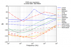
I decided to test the PSRR of an LM317 IC regulator. The results highlight very explicitly the problem I am having. Jack Walton tested this regulator alongside a number of others in articles which I believe were published in Linear Audio. I've attached a graphic of his PSRR test results. You can clearly see the rise in the blue trace indicating a circa 20dB per decade reduction in PSRR.
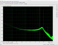
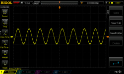
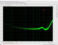
The second pic is a screen grab of ARTA's spectrum analyser while injecting a 20kHz 1Vpp ripple riding on 18V DC into my LM317. Note first of all the sharp drop in noise from about 15k onwards. That I think is the first most glaring clue that something is going wrong (or I'm doing something wrong). The second set of clues are in my PSRR readings:
Hz dBV
50 -65
100 -71.8
500 -96
1k -94.5
2k -93.4
3k -90.5
5k -86.7
10k -78.5
20k -70.7
30k -75.3
40k -76.0
50k -76.1
60k -76.3
70k -75.4
80k -76.0
90k -74.6
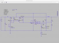
The LM317 is setup pretty much as you might expect: 0.1uF cap at input, 115R and 1kR voltage divider to set the output to 12V, 10uF cap on the adjust pin, 0.1uF on the output followed by a 220uF electrolytic. Attached to the output of the LM317 are two 10W 12R resistors in series generating a load of 0.5A. Once again, I've verified the rail driver output (circuit attached) is providing 1Vpp stimulus at all frequencies used in the test. (It can drive at least 470n at the input of the regulator under test for all frequencies of interest but here it need only drive 100n.)
I've used a short piece of shielded coax cable to connect the output of the LM317 to the input of the preamp. (Shield to ground, inner wire to +ve.)
I wouldn't have thought an LM317 to have an output impedance which would pose problems for the preamp yet something is very wrong out past 10k (if not before). I don't think any of us would expect an LM317 to have flat PSRR from 30kHz to 90kHz and certainly Jack Walton's tests showed this.
Ideas very much welcome...
I decided to test the PSRR of an LM317 IC regulator. The results highlight very explicitly the problem I am having. Jack Walton tested this regulator alongside a number of others in articles which I believe were published in Linear Audio. I've attached a graphic of his PSRR test results. You can clearly see the rise in the blue trace indicating a circa 20dB per decade reduction in PSRR.
The second pic is a screen grab of ARTA's spectrum analyser while injecting a 20kHz 1Vpp ripple riding on 18V DC into my LM317. Note first of all the sharp drop in noise from about 15k onwards. That I think is the first most glaring clue that something is going wrong (or I'm doing something wrong). The second set of clues are in my PSRR readings:
Hz dBV
50 -65
100 -71.8
500 -96
1k -94.5
2k -93.4
3k -90.5
5k -86.7
10k -78.5
20k -70.7
30k -75.3
40k -76.0
50k -76.1
60k -76.3
70k -75.4
80k -76.0
90k -74.6
The LM317 is setup pretty much as you might expect: 0.1uF cap at input, 115R and 1kR voltage divider to set the output to 12V, 10uF cap on the adjust pin, 0.1uF on the output followed by a 220uF electrolytic. Attached to the output of the LM317 are two 10W 12R resistors in series generating a load of 0.5A. Once again, I've verified the rail driver output (circuit attached) is providing 1Vpp stimulus at all frequencies used in the test. (It can drive at least 470n at the input of the regulator under test for all frequencies of interest but here it need only drive 100n.)
I've used a short piece of shielded coax cable to connect the output of the LM317 to the input of the preamp. (Shield to ground, inner wire to +ve.)
I wouldn't have thought an LM317 to have an output impedance which would pose problems for the preamp yet something is very wrong out past 10k (if not before). I don't think any of us would expect an LM317 to have flat PSRR from 30kHz to 90kHz and certainly Jack Walton's tests showed this.
Ideas very much welcome...
Attachments
I used 1V to be consistent with Walt Jung's 1995 articles. Some folks have since suggested that this may be too large a "disturbance" signal.
You can always get one of these: https://www.picotest.com/products_J2111A.html works DC to 40MHz
Have you verified your rail driver circuit's response at the higher frequencies?
You can always get one of these: https://www.picotest.com/products_J2111A.html works DC to 40MHz
 !
!That's for Load Regulation.You can always get one of these: https://www.picotest.com/products_J2111A.html works DC to 40MHz
SGK is trying to test and measure Line Regulation, which calls for the Picotest model 2120A https://www.picotest.com/products_J2120A.html at a cost of $525.
Have you verified your rail driver circuit's response at the higher frequencies?
Yes. But I will do so again. EDIT: what I verified is that with regulator under test connected and its load (24R) connected, the rail driver delivered a 1Vpp sinus at the requisite frequency.
I think I will also try measuring the LM317 without the preamp (leaving all else the same except for caps between reg output and input to sound card).
Last edited:
Yes. But I will do so again. EDIT: what I verified is that with regulator under test connected and its load (24R) connected, the rail driver delivered a 1Vpp sinus at the requisite frequency.
I think I will also try measuring the LM317 without the preamp (leaving all else the same except for caps between reg output and input to sound card).
Connecting a 0.1uF straight at the output of a regulator is in general a very bad idea. It's a pretty safe recipe to make the requlator feedback loop either unstable or dangerously close to instability, in particular if a low ESR cap is used.
@Waly, agreed. The reg was stable but I agree this cap isn't helpful. I was following an old BoM for an old board for which I had retained spares. The boards provided an efficient platform for assembling the reg circuit. I have removed the cap.
I tested the LM317 again without the preamp. I used two 470uF bipolar caps to couple the reg output to my sound card. The results weren't materially different from the test I conducted with the preamp.
Results:
Hz dBV
50 -66.6
100 -72.9
500 -96.7
1k -96.0
2k -94.5
3k -91.5
5k -87.2
10k -79.2
20k -70.3
30k -75.2
40k -76.1
50k -76.3
60k -76.5
70k -75.5
80k -75.9
90k -73.5
These results can be compared directly with those in post 178.
I'm struggling to find a problem with the tests:
* The output of the rail driver shows 1Vpp ripple as a stimulus at all frequencies with no obvious distortion while conducting the tests.
* LM317 testing didn't reveal a material difference between testing with and without the preamp.
* Post 157 tested the frequency response of the preamp / sound card chain by inputing a constant 1mVpp and reading the dBV in ARTA. It produced flat results from 100Hz to 90kHz. If there were a problem with either the sound card or the preamp frequency response surely this test would not produce flat results.
* An impulse response sweep for the sound card suggests it is down just circa 1.5dB at 90kHz.
* If the problem was somehow something to do with coupling the regulator under test to the preamp then the results above would differ materially from those in 178.
Am I missing some combination? (other than my sound card magically doesn't like a voltage regulator in the chain)
Attachments
Last edited:
Maybe it's worth to check your soundcard a bit more, than just an impulse response.
I would take a 0dBV signal from the function gen, use resistor voltage dividers to attenuate it by 60dB to 90dB in probably 6dB intervals, and see what signal level the sound card will measure (keep the wiring between the voltage divider out and soundcard in as short as possible), then repeat with different frequencies.
I would take a 0dBV signal from the function gen, use resistor voltage dividers to attenuate it by 60dB to 90dB in probably 6dB intervals, and see what signal level the sound card will measure (keep the wiring between the voltage divider out and soundcard in as short as possible), then repeat with different frequencies.
I coupled the sound card directly to my signal generator. 10mVpp sinusoidal output. I dialled in test frequencies from 100Hz to 90kHz. The dBV reading in ARTA (cursor on highest peak in the plot) did not move more than 0.3 dbV around -49.3dBV (which equates to 9.7mVpp). So I can only conclude the sound card response is flat (for these purposes). (Were it not flat the test in 157 would not have produced flat results - unless the sound card and preamp coincidentally netted perfectly.)
I did the same test at 30mVpp input. A little more variance across the spectrum, 1dB, but essentially flat.
I did the same test at 30mVpp input. A little more variance across the spectrum, 1dB, but essentially flat.
It may be time to split this thread into a "PSRR measurement" from "noise measurement" which was the initial topic.
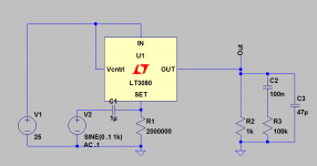
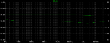
BTW, simpler "rail injector" can be crafted by modulating the "SET" pin of the LT3080 single resistor DC regulator with an a.c. stimulus. You should be good to 200kHz.
BTW, simpler "rail injector" can be crafted by modulating the "SET" pin of the LT3080 single resistor DC regulator with an a.c. stimulus. You should be good to 200kHz.
Attachments
The rail driver suggested by Mark had a convenient benefit: I already had parts and a PCB that could do the job. It would seem to do the job well as I have checked the input to the reg-under-test at all frequencies of interest and it continues to deliver the 1Vpp stimulus.
Walt Jung & Gary Galo tried that using the LM317 back in the day, but couldn't get the performance they wanted. So they went with 1st generation Pooge discrete transistor voltage regulators, feeding the sinusoidal input voltage into the error amplifier transistor's base.
I used Walt's injector from 1995 AX series for the LA article!
Janneman first mentioned the LT3080 (as an amplifier) to me when the chip first came out.
- Status
- This old topic is closed. If you want to reopen this topic, contact a moderator using the "Report Post" button.
- Home
- Amplifiers
- Power Supplies
- Measuring PSRR