An attempt at putting this measurement amplifier to work measuring PSRR of a PSU I have been working on. Comments welcome!
http://www.diyaudio.com/forums/powe...ild-sdip-bridge-rectifiers-8.html#post4853030
http://www.diyaudio.com/forums/powe...ild-sdip-bridge-rectifiers-8.html#post4853030
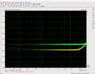
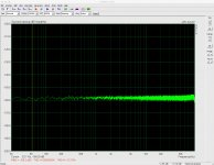
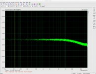
I seem to be encountering a problem when using my measurement amplifier with ARTA and an ESI Juli@ to measure PSRR (see link in previous post). The issue is highlighted by shorting the input to the preamp with first a 1k resistor and secondly a 470k resistor (the largest I have to hand). There is a sharp rolloff in the measured noise for the latter above about 10k.
Am I right to think that the slight rolloff in my sound card's frequency response gets amplified in the results? (Or some sort of slew rate issue?)
Am I right to think that the slight rolloff in my sound card's frequency response gets amplified in the results? (Or some sort of slew rate issue?)
Attachments
Given the amplification is occurring before anything hits the sound card I wouldn't expect any impact from the sound card except its rather small rolloff in frequency response (-1.5dB) between 20kHz and 90kHz.
If I have done my calculations correctly, a 470k resistor should show a flat noise spectrum of 87nV/rtHz which is -141dBV. I'm not getting this at all. Surely this indicates an issue with the preamp gain / freq response?
If I have done my calculations correctly, a 470k resistor should show a flat noise spectrum of 87nV/rtHz which is -141dBV. I'm not getting this at all. Surely this indicates an issue with the preamp gain / freq response?
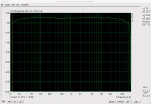
I decided to test the frequency response of the preamp by coupling up my signal generator to the input and looking at the spectrum analyser in ARTA (set to dBV). As my signal generator can't go below 4mVpp output I used a simple 1kR and 100R voltage divider at the input of the preamp and dialled in 11mVpp at the generator. Unless I am going kooky or have made another basic error it would seem the frequency response of the pre-amp/soundcard/ARTA setup is flat (enough for my purposes).
At all stimulus frequencies the RMS figure in ARTA read between -69.6 and -69.8 dBV. (Only at 500Hz was it 69.6dBV, otherwise mostly 69.7 except for one or two of the higher frequencies.) Cursor readings at the stimulation frequencies were as follows:
100Hz -69.75 dBV
500 -70.25
1k -70.32
2k -70.20
3k -69.98
5k -70.13
10k -70.83
20k -69.80
30k -70.35
40k -70.02
50k -70.02
60k -70.40
70k -69.83
80k -70.92
90k -69.97
I think I am right in doing the following calculation. I had entered a preamp gain of 1000 in ARTA (the nominal value for the preamp circuit). -69.7dBV is 926uV. My generator stimulus was 11mVpp. If my voltage divider were perfect the actual gain of the pre-amp is 926. The resistors in the voltage divider were 2%. My multimeter can measure to 1.2% + 2 digits at 400R and 1% +2 digits at 4k. I measured 1.003k Ohms and 99.4 Ohms respectively. So my pre-amp gain may well be a little over 926x.
So doesn't seem too bad...
Damned if I understand the measurement of the 470k resistor...
If I have done my calculations correctly, a 470k resistor should show a flat noise spectrum of 87nV/rtHz which is -141dBV. I'm not getting this at all. Surely this indicates an issue with the preamp gain / freq response?
The input is driving 8 BF862 in parallel, each having input capacitance of 10pF.
I suspect your 470k resistor has formed a RC filter with the input capacitance of the BF862s.
Ah, that accounts for my missing 66pF.
F-3dB of 5kHz needs ~ 67pF with the 470k to roll off.
But I discounted that as a reason because I could not see a parasitic of the resistor nor how it was attached that could be within a couple of decades of 67pF.
I can read off approx 15 to 20dB roll off over one decade of frequency. Gets pretty close to a 1pole filter.
Now repeat the 1K with 10k and 100k as the input loading resistors.
A pattern should emerge and maybe show where the extra noise begins to get lost.
Last edited:
Hi cwtim01 and AndrewT. Thanks. Excuse the potentially stupid question but while that might explain the roll-off, what about the fact that I see circa -150dBV/rtHz at lower frequencies and not -141dB? Is my calculation off?
The concern regarding this originated testing PSRR of a high performance regulator circuit. Mark Johnson quite legitimately raised the question here that other regulator circuits tested by Jack Walton exhibited a circa 20dB/decade degradation in performance past about 10kHz and yet my circuit under test did not. As you will see in that thread I went on to also test the performance of a LM7812 using the same methodology and test equipment.
When I shorted the input of the preamp with the large resistance value it appeared to reveal a roll-off in frequency response that I was struggling to understand and one which seemed close to potentially explaining Mark's observation. However, I would have thought that if there were a problem with the frequency response of the pre-amp then it would have revealed itself in the 1k plot as well. My tests today in post 157 would seem to suggest all is well with it.
I would be very surprised if the output of the regulator presented a source impedance to the pre-amp so high as to cause an RC filter with the BF862 input capacitance a la the 470k...
... what about the fact that I see circa -150dBV/rtHz at lower frequencies and not -141dB? Is my calculation off?
I'm not sure you can just read out -150dBV from the graph, and then call it -150dBV/rtHz. Refer to this post from Samuel.
I read some posts about your regulator project. I don't know much about regulators, but I'll give a try:
- 20dB/decade degradation in PSRR of many regulators, I would think that's due to reduced open loop gain at higher frequency, so the error amplifier has less negative feedback to correct the output.
- Rolloff with a source resistance of 470K reported in your post #155 - RC low pass filtering.
Of course they don't....I would be very surprised if the output of the regulator presented a source impedance to the pre-amp so high
And yet observing the power spectral density of a 1k resistor was considered one test of the pre-amp's correctness. I will look at 10k and 100k at some point today.
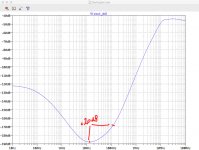
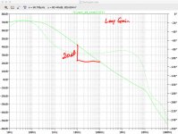
Indeed, there is a dominant pole in the loop gain plot causing a 20dB/decade rolloff in loop gain available for feedback error correction (see attached sim of the Darlington component to the reg under test). And an RC filter causes a pole also. Absent other poles and zeroes a 20dB rolloff in PSRR for a regulator is to be expected. It could be that the level of PSRR is such that this reduced PSRR only rises through the noise floor at frequencies higher than 90kHz but the measurements I took showed residuals of stimulation frequencies poking up above the noise floor at lower frequencies. (See charts here.)
Indeed, there is a dominant pole in the loop gain plot causing a 20dB/decade rolloff in loop gain available for feedback error correction (see attached sim of the Darlington component to the reg under test). And an RC filter causes a pole also. Absent other poles and zeroes a 20dB rolloff in PSRR for a regulator is to be expected. It could be that the level of PSRR is such that this reduced PSRR only rises through the noise floor at frequencies higher than 90kHz but the measurements I took showed residuals of stimulation frequencies poking up above the noise floor at lower frequencies. (See charts here.)
Attachments
Last edited:
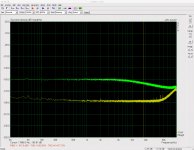
Looks like the 1k, 10k and 100k give about the correct level of noise that you expected.
Is that right?
The 100k is just starting to show a bit of roll-off. Does that tally with the input capacitance of the stage?
I can't explain why the 470k has a similar level to the 100k. But the roll-off does seem to tally with the 60ish pF of input capacitance.
I think you can draw from this that your amplifying stage does not suit high source impedances. Keeping below 1k leaves you lot's of leaway and if you must measure signals that have a higher output impedance you can maybe find how to correct for a measurement error that might otherwise have been included but unnoticed.
Perhaps I should have been clearer above. My concern was that a 20dB per decade roll off in the frequency response in the test setup was masking a 20dB per decade decline in PSRR.
If you refer to the figure 17 & 18 of the article, you'll find the frequency response of the pre-amp, and I don't see how it'll mask your PSRR measurement below 100kHz. Even if your regulator have an output impedance of 25R, the -3dB corner frequency will be above 1MHz (figure 18).
Unless you want to design a regulator with output impedance above 1k ohm, the RC filter won't get in your way.
@cwtim01 - yes, indeed. Of course, the problem with building a component of the test setup to measure something is that you must first determine that this component is working correctly. So if it is indeed operating to spec it shouldn't mask the performance (favourably or unfavourably) of the regulator DUT.
@AndrewT, I understand an approximation of the Johnson-Nyqvist thermal noise of a resistor at room temp is given by 0.13*SQRT(R) nV/rtHz. So:
1K 4.1nV/rtHz = -168dBV
10k 13nV/rtHz = -158dBV
100k 41.1nV/rtHz = -148dBV
So 1k and 10k look about right, 100k much less so and 470k not at all. But then I wasn't really intending to use the pre-amp with such high source impedances. The 470k resistor test was, it would seem, a red herring.
It would seem reasonable to conclude that from the flat nature of the 1k and 10k resistor tests and of the "11mVpp attenuated to 1mVpp input" test (post 157) that I have managed to assemble the pre-amp for good working order. It looks like the gain is perhaps a little less than expected, but not much. (I'm unsure whether to adjust the pre-amp gain value in ARTA from its nominal 1000x to something closer to 926x. Probably would make sense.)
The other piece of equipment that had to be made to test the regulator was a rail driver (see other thread). I examined the input stimulus ripple at all tested frequencies with the regulator DUT and its load attached and that too would seem to operate properly.
So maybe measured regulator PSRR is reasonable and the inevitable loss in PSRR at higher frequencies will only be noticeable with tests conducted at such. Dunno. If my testing is valid this regulator would seem to be a superb performer. (He says with extraordinary caution...)
So if it is indeed operating to spec it shouldn't mask the performance (favourably or unfavourably) of the regulator DUT. @AndrewT, I understand an approximation of the Johnson-Nyqvist thermal noise of a resistor at room temp is given by 0.13*SQRT(R) nV/rtHz. So:
1K 4.1nV/rtHz = -168dBV
10k 13nV/rtHz = -158dBV
100k 41.1nV/rtHz = -148dBV
So 1k and 10k look about right, 100k much less so and 470k not at all. But then I wasn't really intending to use the pre-amp with such high source impedances. The 470k resistor test was, it would seem, a red herring.
It would seem reasonable to conclude that from the flat nature of the 1k and 10k resistor tests and of the "11mVpp attenuated to 1mVpp input" test (post 157) that I have managed to assemble the pre-amp for good working order. It looks like the gain is perhaps a little less than expected, but not much. (I'm unsure whether to adjust the pre-amp gain value in ARTA from its nominal 1000x to something closer to 926x. Probably would make sense.)
The other piece of equipment that had to be made to test the regulator was a rail driver (see other thread). I examined the input stimulus ripple at all tested frequencies with the regulator DUT and its load attached and that too would seem to operate properly.
So maybe measured regulator PSRR is reasonable and the inevitable loss in PSRR at higher frequencies will only be noticeable with tests conducted at such. Dunno. If my testing is valid this regulator would seem to be a superb performer. (He says with extraordinary caution...)
Last edited:
But measurements of the LM7812 which showed no significant roll-off in PSRR at the upper end of the frequency range make me deeply suspicious of the test setup
... the problem with building a component of the test setup to measure something is that you must first determine that this component is working correctly ...
Very true. Why don't you manually (using your function generator and scope) measure the frequency response of your pre-amp build and see what you get. The output impedance of your function gen will be quite higher than your regulator, so if you get a flat response to 100kHz with your function gen, the response with the regulator can only be flatter.
yes I did that subsequently - post 157
So at least you know the frequency response of the pre-amp is not the culprit of your measurement issues then.
I can't comment on the rest of your measurement setup, good luck
- Status
- This old topic is closed. If you want to reopen this topic, contact a moderator using the "Report Post" button.
- Home
- Amplifiers
- Power Supplies
- Measuring PSRR