That looks OK. If there were significant AC present then the caps would have a voltage across them. The small voltage you see will be a consequence of the meter being effectively 'floating' because the diode is non conducting.
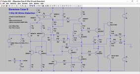
Look at the bottom left of the circuit here. The output of the amplifier is 4 volts peak to peak, the cap voltage is 4 volts less the forward vdrop of the diode. So any problem below that diode threshold would not register. Having said that, even if there were a low amplitude instability, it almost certainly wouldn't cause noticeable heating.
Look at the bottom left of the circuit here. The output of the amplifier is 4 volts peak to peak, the cap voltage is 4 volts less the forward vdrop of the diode. So any problem below that diode threshold would not register. Having said that, even if there were a low amplitude instability, it almost certainly wouldn't cause noticeable heating.
Attachments
Here is what I measured.
DC Offset before connecting diodes/caps.
Left: 7.4mV
Right: -4mV
Across Caps.
Left: 2.4mV
Right: -1.6mV
Hi,
Can you retest it with 0.047uf because the circuit has 2 x 0.1uf in series ?
Regards.
OK, so where are we with things? Wait and see if it acts up again and do the diode/cap test then. Right now, it is still playing fine. Played last night again (Covers on, no fan) for about 4 hours, mix iPod and LPs. No issues, no excess heat.
(I saved your image, but when I zoom in on it, I can't make out any of the diagram numbers)
(I saved your image, but when I zoom in on it, I can't make out any of the diagram numbers)
Hi,
Can you retest it with 0.047uf because the circuit has 2 x 0.1uf in series ?
Regards.
I'll have to swing by the Shack to pick up some of those as I don't have any on hand. Are you referring to the 0.1uF caps at C39/C41?
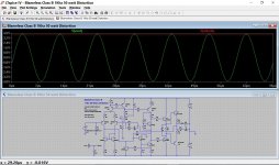
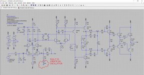
The diagram is just a poweramp outputting 4 volts pk/pk @ 100kHz. The diode and cap at the bottom right rectify this AC output and generate a DC voltage in proportion to the peak less the forward drop of the diode.
The node vout on the diode means it is in electrical contact with vout at the right of the diagram (the main amplifier output). It just saves drawing a wire")
I guess so.
The node vout on the diode means it is in electrical contact with vout at the right of the diagram (the main amplifier output). It just saves drawing a wire
OK, so where are we with things? Wait and see if it acts up again and do the diode/cap test then.
I guess so.
Attachments
Hi,
Can you retest it with 0.047uf because the circuit has 2 x 0.1uf in series ?
Regards.
I don't follow what you are getting at here
I'll have to swing by the Shack to pick up some of those as I don't have any on hand. Are you referring to the 0.1uF caps at C39/C41?
Forget it. I was thinking of something else.
Without any input signal, try to increase the volume and see if there is any voltage change across the 0.1uf cap.
Oh. Should have read latest posts. Picked up a pair of .047 caps and measured nearly the same numbers as the .1 caps. Should I switch back to .1s and try turning up the volume?
At this point not sure it matters since it isnt acting up.
The amp played last night again for over 6 hours, no issues.
At this point not sure it matters since it isnt acting up.
The amp played last night again for over 6 hours, no issues.
Well, no bias pots to set on main amp. Only on the Phono/EQ. It was acting up on CD and Phono separately. Maybe those bias ICs just needed warming up to get things playing right . Dunno. I replaced cap on left but right was the original channel w bad voltages. It cured itself and maybe I fixed the left.
. Dunno. I replaced cap on left but right was the original channel w bad voltages. It cured itself and maybe I fixed the left.Remember that you replaced some components. Components were soldered/desoldered.
Components with bad solder joints or maybe moisture are possibilities to be considered. Moisture goes away with heating.
Sometimes you can also find external leakage between transistor or IC legs and after heating them they go away or are reduced.
Cleaning circuit boards can eliminate some problems like residues.
Maybe some faulty electrolytic capacitor you replaced.
Probably after so many things you did the problem is gone


New update/findings
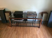
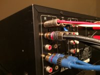
Sunday I moved the amp and entertainment stand as we are painting the basement. Plugged everything back in and went to play a CD and no music. Hear the initial relays click on, and then they clicked again within seconds. WTH? Shut it off and took a look at my connections on the back (RCAs from TT, CD player, Aux/iPod). This was something I noticed when I took the back cover off while working on the Phono/EQ board a few weeks back. The RCA inputs have very small rubber insulators around each jack. Well, when I plugged everything back in, I pushed the connectors on so far that they were coming into contact with the chassis. I pulled them off a bit, and turned things on and music played fine. With newer, heavy duty RCA cables (Monster) it is very easy to push them on too far and have them touch the back of the amp.
So my question is could this grounding of RCA jacks lead to the issues I have been having (bad voltages/oscillation)? This could be why the right channel fixed itself, and the replaced caps fixed the left channel.
I have posted pix of the RCA jacks so you can see there is very little to stop the cable connectors from coming into contact with the chassis.
Attachments
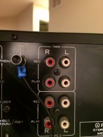
Its normal for input sockets to be insulated from the chassis because to do otherwise would compromise the grounding and lead to hum/buzzes etc. Each socket has to be grounded to the correct point in the amplifier and not just use a common ground like the chassis.
You can prove the theory by connecting the plug outers to the grounding screw that the turntable uses. I would be very surprised if it caused anything like oscillation.
You can prove the theory by connecting the plug outers to the grounding screw that the turntable uses. I would be very surprised if it caused anything like oscillation.
I used LTSpice to simulate the amplifier circuit to see how I could introduce a fault that would lead to an oscillation.
I was expecting to be able to alter the phase shift of the signal around the different circuit stages to get the amplifier to oscillate.
The amplifier is made of multiple stages and I am not familiar with the use of RC filters across the collectors of differential transistor pairs. I wanted to see what could happen if the properties of the RC networks were altered by changing the capacitance value.
RESULTS :
I could not create an oscillation by altering the value of any capacitor.
Altering the RC networks across the differential pairs only affects the frequency response of the amplifier.
From the simulation, it appears that Pioneer have chosen to maintain a flat frequency response. Changes in those RC networks characteristics have a direct impact on the frequency response of the amplifier.
ONE WAIT TO MAKE THE AMP TO OSCILLATE :
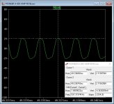
The single way that I found to make the amplifier to oscillate is by removing the reference to the common ground from the feedback network. See the jpgs enclosed.
I was expecting to be able to alter the phase shift of the signal around the different circuit stages to get the amplifier to oscillate.
The amplifier is made of multiple stages and I am not familiar with the use of RC filters across the collectors of differential transistor pairs. I wanted to see what could happen if the properties of the RC networks were altered by changing the capacitance value.
RESULTS :
I could not create an oscillation by altering the value of any capacitor.
Altering the RC networks across the differential pairs only affects the frequency response of the amplifier.
From the simulation, it appears that Pioneer have chosen to maintain a flat frequency response. Changes in those RC networks characteristics have a direct impact on the frequency response of the amplifier.
ONE WAIT TO MAKE THE AMP TO OSCILLATE :
The single way that I found to make the amplifier to oscillate is by removing the reference to the common ground from the feedback network. See the jpgs enclosed.
Attachments
- Status
- This old topic is closed. If you want to reopen this topic, contact a moderator using the "Report Post" button.
- Home
- Amplifiers
- Solid State
- Pioneer A88-x with Bad Channel