Why would you need C2 ?
The Tx output shouldn't have any DC ?
Patrick
You are right, working for months on it and it never appeared in my mind, funny... will try it later without C2.
First I want to experiment more with the crossfeed values. The 18k and 27 K Ohm resistors. I find the crossfeed a bit to subtle, so I think I want to lower the 27k resistors resistors to have more impact.
Thanks,
Walter
Getting rid of the cap in signal path can only be of benefit.
You might want to play with both values 18k & 27k.
Get 2x 2-gang 50k linear pots and play with them until you get what you want.
Then replace with fixed resistors.
We NOW also have a trick to incorporate the volume control pot (10k log) as part of the Cross Feed.
Will publish later either in the F5-HA or ZGF thread, when well proven.
Patrick
One more point if I may.
Your Tx is designed for 15k load (AC) if I am not wrong, but you are using it to drive the 5k input impedance of your follower.
Maybe you should consider changing R6, 24 to 30k.
And then R15,23 wants to be >18k for those Fairchild FETs.
You might also want a trimmer across R15,23 for DC offset adjust, depending on how perfect your Vgs matching is at temperature.
Patrick
Firstwatt B1 DIY
Hello,
I would like to show you my first diy project that i started three years ago. After some work it now works fine and i like the sound very much. The pcbs are point to point wired, the chassis is completely selfmade, but not selfdesigned... I would never do this metal-work again (too expencive and takes too much time). As soon as my aleph-x and my pumpkin are working properly, i will post a few more pictures.
Greetings, Michael
Attachments
The schematics in #3611 suggested different values for the MOSFET source resistors for different bias currents.
A quick hand calculation shows that :
at 3.3R 160mA bias, output impedance ~ 2.8R
at 10R 60mA bias, output impedance ~ 8R
at 15R 40mA bias, output impedance ~ 13R
at 22R 27mA bias, output impedance ~ 19R
And of course the output impedance is not totally linear.
Since this is a ZGF amp, there is no NFB to reduce the intrinsic output impedance further.
If you have a low impedance headphone (e.g. 50R), you might well wish to stick to 160mA bias at least.
Patrick
One more point if I may.
Your Tx is designed for 15k load (AC) if I am not wrong, but you are using it to drive the 5k input impedance of your follower.
Maybe you should consider changing R6, 24 to 30k.
And then R15,23 wants to be >18k for those Fairchild FETs.
You might also want a trimmer across R15,23 for DC offset adjust, depending on how perfect your Vgs matching is at temperature.
Patrick
You certainly may, much appreciated.
I understand what you mean, I'm loading the Edcor trafo too much with the 5K impedance of the output stage. And it might fall off too quickly at high frequencies that way.
I looked at the official M2 schematics and Nelson uses 47k on that position.
Hate to unplug the output boards from the chassis, but maybe if I cut one side of the 10K resistor, I can solder an additional 22K in the circuit resulting in 32Kohm.
In this latest version I use best matched 2SK2013/2Sj313 Toshibas from NicMac.
The FQP's are in the prototype in the first picture, they do indeed have much higher Vgs needed, around 5.7 V instead of around 2.5 - 3 volts for the Toshibas.
So I hope I'm good with the R15, R23 at 10K.
Thanks, Walter
If you have a low impedance headphone (e.g. 50R), you might well wish to stick to 160mA bias at least.
Patrick
No, I have a 250 Ohm Beyerdynamic
")
> but maybe if I cut one side of the 10K resistor, I can solder an additional 22K in the circuit resulting in 32Kohm.
That works fine.
> In this latest version I use best matched 2SK2013/2Sj313 Toshibas from NicMac.
> So I hope I'm good with the R15, R23 at 10K.
Yes.
Patrick
That works fine.
> In this latest version I use best matched 2SK2013/2Sj313 Toshibas from NicMac.
> So I hope I'm good with the R15, R23 at 10K.
Yes.
Patrick
Hello,
I would like to show you my first diy project that i started three years ago. After some work it now works fine and i like the sound very much. The pcbs are point to point wired, the chassis is completely selfmade, but not selfdesigned... I would never do this metal-work again (too expencive and takes too much time). As soon as my aleph-x and my pumpkin are working properly, i will post a few more pictures.
Greetings, Michael
Michael love your metal-work! So keep on doing it
I agree building a chassis is expensive, I did my Aleph J myself, but it would have been cheaper to buy one at Ebay or a Modushop 5U.
How did you do your frontplate?
Michael love your metal-work! So keep on doing it
I agree building a chassis is expensive, I did my Aleph J myself, but it would have been cheaper to buy one at Ebay or a Modushop 5U.
How did you do your frontplate?
Nice to hear that, walter! Well, a friend of mine has access to an cnc machine. The chassis is made of 5 and 10mm alu and quite heavy (in relation to the interior...). Most of the work was the construction and finding out the dimensioning from pictures. For my pumpkin preamp i bought an modushop case and now try to modify it. I ll post pictures, when the front plate arrives!
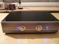
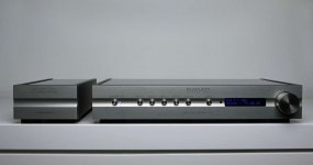
View attachment 555550 It took me some months to finish, but finally it's as intended in a nice chassis.
It's a dual mono headphone amp, with the M2 gain stage, with the Diyaudio headphone amp output stage with the Jung/Didden Super regulator boards and not to forget the crossfeed circuit from EUVL from his F5-HA Description V1.4 document.
It was a nice journey back in time, to make my own PCB's, with all the chemicals and so on
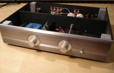
Lessons learned: design one big PCB with everything on it, connecting all those little PCbs is a lot of work
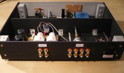
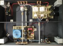
The Edcor's did pick up a lot of hum from the initially placed R-core transformer. Changing to toroid's and placing them this way, solved the hum problem.
The outputstage has 3.3 Ohm source resistors, resulting in a 180mA bias at 15.0 Volts. Enough to drive every headphone, I guess.
Regulators and output stage generate about 10 Watts of heat each channel which can be easily dissipated by the side panels.
Resulting in a warm, 42 degrees Celsius amplifier chassis...
With the crossfeed and relais switch board, I can select to listen to only the outputstage, outputstage with M2 gain and outputstage with M2 gain and crossfeed.
Off course it sounds very, very nice!
Walter
Very good looking job once again!
Did you make the chassis yourself? I am wondering how you managed cutting those cooling slots on the top cover?
If your chassis is at 42C how much are the 2013/313 running at? And what is considered a safe high temp for these as measured on the mounting tab? I ask since I am using these in my current build of a BA3 balanced pre.
BTW I have used your tip of using 3M VHB tape. Works great. Thanks.
Nash
That is a hifi2000 galaxy 2U chassis with customized front and back panels.
Indeed!
A CNC is a must for quality work.......look at the pictures of the B1 here.
CNC from scratch.
Almost reminds me of Tiroler's work....almost, finish is not as good ...but close.
The finish was quite frustrating and not what i expected. I received the plain/shiny aluminium, went to an sandjet cabine and after that to an expencive anodisation. The result was looking great - for about 5 minutes. After putting the parts together there were fingerprints on it, tried to clean, impossible. The surface was as hard as sandpaper and impossible to be cleaned. So i airbrushed it black. Also not so easy for an hobbyist without a dustfree room. But it was my first try and the result is okay for me. Maybe i will put the labeling on if find the time. The b1 from tiroler looks really great!!

Walter:
Congratulations -- another well-conceived, beautifully executed project! Exactly how big is your audio equipment collection these days?
Regards,
Scott
It's getting a little to big
if they stay in the corner like this....Attachments
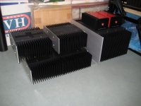
It's getting a little to big
Your wife must be a very understanding person!! I would never get away with that!!
- Home
- Amplifiers
- Pass Labs
- Pictures of your diy Pass amplifier