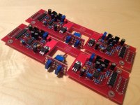
Well, 1 hour listening session with 2 PCB as differential input (no more bridge), very good separation of the chanel which immediately brings a scene of instruments instead of music in the center. Also inverting one chanel input (very easy by swaping In+ and In-) and reverting the loudspeaker wiring gave an ultimate Bass experience ! because usually the bass are spread equally on both chanel and then by inverting one chanel, you equally pump on both rail and then get about twice the Joule capacity of each cap. this single hypex is very great in this condition
Plug your FO, find a good flac or wav for this song and you ll get stuck:
https://www.youtube.com/watch?v=MOVuGQTuTBc
LC, please put your hands on the bench and design us a Differential FO version 1.5!
Thanks for sharing Max, I like your chassis layout.

THAT 1200 provides good solution for diff input, low supply current makes it ideal to connect it to SMPS's auxillary supply. THAT 1200 can be located on unbal/bal input connectors/switch PCB at the back plate.
Differential input FO, did you think on discrete or IC solution?
L.C.

Wish I could, currently working on a certain OEM project, lots of good stuff available in the system, Analog DAC just one of them ..Please share.

Ordinary amp:
Differential amp (R1=R2, R3=R4):
Which is also perfectly balanced...
An externally hosted image should be here but it was not working when we last tested it.
Differential amp (R1=R2, R3=R4):
An externally hosted image should be here but it was not working when we last tested it.
Which is also perfectly balanced...
Ordinary amp:
Differential amp (R1=R2, R3=R4):
Which is also perfectly balanced...
Seriously?
Ordinary amp:
An externally hosted image should be here but it was not working when we last tested it.
Differential amp (R1=R2, R3=R4):
An externally hosted image should be here but it was not working when we last tested it.
Which is also perfectly balanced...
No, that is not 'perfectly balanced.'
See an excellent explanation here:
Balanced loading
I agree with LC. If you want to implement a balanced input on a non balanced design, then use the THAT 1200 chip, or transformer or instrumentation amplifier circuit
Best,
Anand.
My YT channel:
https://www.youtube.com/channel/UCqN7Sv1pWxRDMmfbzBSyH6A
Few from inside:
https://youtu.be/c8s2XbPpRKI?list=PL46750BE22B756146
https://youtu.be/F6k-r0jYlLc?list=PL46750BE22B756146
https://youtu.be/GyfhZkMA0bU?list=PL46750BE22B756146
https://youtu.be/KzHEWod3rmU?list=PL46750BE22B756146
...
Enjoy
https://www.youtube.com/channel/UCqN7Sv1pWxRDMmfbzBSyH6A
Few from inside:
https://youtu.be/c8s2XbPpRKI?list=PL46750BE22B756146
https://youtu.be/F6k-r0jYlLc?list=PL46750BE22B756146
https://youtu.be/GyfhZkMA0bU?list=PL46750BE22B756146
https://youtu.be/KzHEWod3rmU?list=PL46750BE22B756146
...
Enjoy
It is. An excellent explanation here:No, that is not 'perfectly balanced.'
The G Word
The "explanation" is about volume control / attenuator circuit. It is not balanced. But the difference amp - is. The only 'downside' is the low input impedance (as long as you want keep noise low). If you want that to be higher or want a volume control - a buffer (instrumentation amp), or some other interface is needed...See an excellent explanation here:
Balanced loading
Ok. We'll agree to disagree then - to a point . I agree with Bruno, and I have read his excellent writeup in the G word, [and differential pre project here on DIYaudio] but I don't agree with your drawing and would not use that in my own designs, particularly considering how noisy resistors get at much higher values. He even states Bill Whitlock's patented THAT1200 circuit as being excellent for maintaining low CMRR, but now I digress.
If your system can handle a low input impedance then ok. If not, then there are other options.
Best,
Anand.
. I agree with Bruno, and I have read his excellent writeup in the G word, [and differential pre project here on DIYaudio] but I don't agree with your drawing and would not use that in my own designs, particularly considering how noisy resistors get at much higher values. He even states Bill Whitlock's patented THAT1200 circuit as being excellent for maintaining low CMRR, but now I digress. If your system can handle a low input impedance then ok. If not, then there are other options.
Best,
Anand.
Last edited:
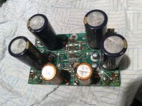
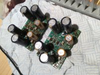
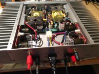
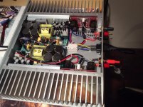
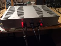
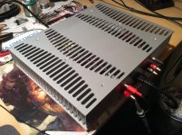
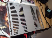
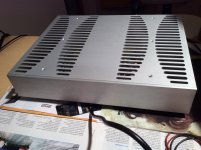
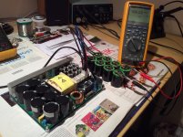
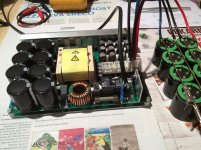
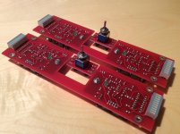
First One module began like this..
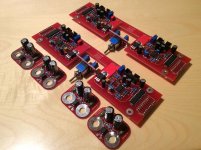
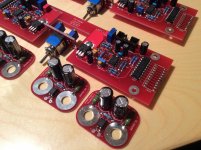
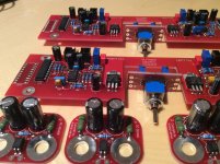
In 2013 the first First One v1.1 module started its life in a chassis below. Lately, after reading few positive reviews my friend was finally convinced and asked me to make an upgrade. Here are some photos of job done.
In 2013 the first First One v1.1 module started its life in a chassis below. Lately, after reading few positive reviews my friend was finally convinced and asked me to make an upgrade. Here are some photos of job done.
Attachments
-
 IMG_0693.jpg475.4 KB · Views: 651
 -
 IMG_0692.jpg527.8 KB · Views: 231
 -
 IMG_0686.jpg469 KB · Views: 229
 -
 IMG_0690.jpg541.2 KB · Views: 229
 -
 IMG_0689.jpg478.3 KB · Views: 226
 -
 IMG_0691.jpg494.8 KB · Views: 236
 -
 IMG_0694.JPG970.2 KB · Views: 185
 -
 IMG_0698.jpg465.8 KB · Views: 133
 -
 IMG_0695.jpg436.9 KB · Views: 136
 -
 IMG_0697.jpg428.9 KB · Views: 130
I could, currently working on a certain OEM project, lots of good stuff available in the system, Analog DAC just one of them ..Please share.
What to say so far, I honestly think most of you don't know what you have..

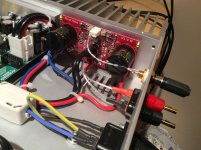
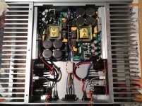
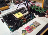
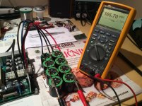
Playing with the beast
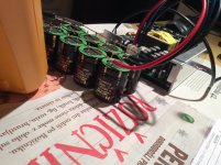
Two SMPS3kA700 just arrived on the testbench. Both turn-on with extra 26 mF caps on the rails without any problem. 200 J of energy storage per channel will be more than enough for the First One L module.
Two SMPS3kA700 just arrived on the testbench. Both turn-on with extra 26 mF caps on the rails without any problem. 200 J of energy storage per channel will be more than enough for the First One L module.
Attachments
Looking forward to Analog Dac. Some Progress already?
Last year voicing of FO M took place, this year FO L testing in progress. Since the main system is on the top level, voicing will be much easier and faster. Stay tuned.
LazyCat: What bandwidth did you use to measure SNR of the FO M?
Because I am aware of some independent measurement of FO M on the AP, and the SNR @ BW 22kHz was measured worse than 110dB which is specified in the datasheet.
It would be better if you could update it to contain also bandwidth and also the expected absolute noise floor with the shorted input.
Thanks.
That is at least to say opinion of unauthenticated 'independent' source which you leisurely and irresponsibly transfer here as it was a pure gold. Would have to do way better than this. As stated many times I will not lead any kind of theoretical debate here as it is commercial thread, but hey you can open new thread in no time on some other parts of the forum and kindly invite people to cooperate.
Regards, L.C.
Regards, L.C.
- Home
- Vendor's Bazaar
- First One - mosFET amplifier module