Now back to the overall question presented; is there a sweet spot to place the bias current?
I you need a magic number, you must find it empirically, with the data provided by manufacturer, to be polite only can say that your transformer is not among the best.
Copper loss on the primary is given by
Ploss [%] = 100 Rp / (Zp + Rp) ≈ 6.9 %
For a decent transformer you must expect at most 3 %, and the same for core loss.
Well, not really.
Chris
Please clarify, enlighten me, I am too dumb for these things.
it is increasingly black art
Hello Chris,
I do not know if I can help you. Transformers are as much black art as they are science. They are more trial & error technology and engineering than they are physics. Take a look at the lack of spice models.
All that said consider a blank sheet of graph paper with X and Y scales, quadrant I where both X and Y are positive is where the permeability of the single end transformer lives. As current goes up flux goes up at a perhaps an exponentially decreasing (put it in MATLAB and do some curve fitting) rate to a maximum we call saturation. This is a curve not a linear line, pardon the intended redundancy.
Graphically think of the output as a reflection of the input from this curve. The output is necessarily nonlinear.
Beyond that it is increasingly black art, start adding variables to the SPICE model.
DT
Last edited:
This is a poor description of the hysteresis of the B/H magnetization curve.
And this is a poor description of magnetic hysteresis curve.
First you must decide what do you use, the magnetic field B, or magnetization M, they are related, but not the same
B = H + 4π M
Then you can plot B vs H, or M vs H.
It also overlooks the main reason to build single-ended amplifiers with output transformers, the changing slope of the curve through zero axis (permeability).
This is a poor definition of permeability, and in fact, in single ended output transformers the whole hysteresis loop lies on the first quadrant and maybe is a truism, but surprisingly, higher movability of magnetic domains it produces when field B has a zero crossing, B=0 on magnetic hysteresis curve, on that case, Barkhausen noise, BHN, reaches its maximum.
My question about the link between hysteresis and linearity remains.
Linearity comes fron line, for an homogeneous and isotropic medium
B = μ H
Magnetic permeability, μ, is a constant and B vs H is a straight line, then we say that the response of the medium is linear.
As V=f(B) and I=f(H) and the functions are linear, it follows that
V = k I
If the medium has hysteresis, μ is a tensor and linearity goes to hell.
This is a curve not a linear line, pardon the intended redundancy.
Graphically think of the output as a reflection of the input from this curve. The output is necessarily nonlinear.
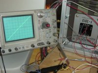
Single Ended Black Magic
Not a perfect straight line, but almost...
Attachments
found that sweet spot
Hey Popilin,
I am beginning to like you.
You must have found that sweet spot.
DT
Single Ended Black Magic

Not a perfect straight line, but almost...
Hey Popilin,
I am beginning to like you.
You must have found that sweet spot.
DT
Only if the secondary is open-circuit, so no transformer action.DualTriode said:The required AC swing occupies very much of the available space on the magnetization curve.
I am not feeling the love.
Dr. Dave,
I am not feeling the love.
You snipped a few of my words out of context.
Is there malice in your intent?
DT
Only if the secondary is open-circuit, so no transformer action.
Dr. Dave,
I am not feeling the love.
You snipped a few of my words out of context.
Is there malice in your intent?
DT
You must have found that sweet spot.
Not me, but Tamura, and the picture was taken from the link on post #25.
Only if the secondary is open-circuit, so no transformer action.
No, DT was right, in a SE OPT always you have
B = Bdc + Bac
For a given DC bias current, which in turn gives Bdc, the available magnetic field in the transformer is Bac, which in turn limit the voltage AC swing.
Definitely not! I am just puzzled that you seem to be continuing to treat an SE OPT as though it is just a choke, with no secondary current and hence flux determined by primary current alone. Am I misunderstanding you?DualTriode said:Is there malice in your intent?
sorted that out
Dr. Dave,
Thank you.
Now that we have that sorted that out.
let’s assume that there is an 8 ohm resistor connected to the secondary winding. We have the secondary winding and load accounted for, yes it is a transformer. Also assume we are attempting to operate this transformer at the specified 10 watt power output. A couple more assumptions, if you will, we want to select a bias current that allows maximum AC swing while avoiding the zero crossing and the saturation ends of the curve.
To answer your question: at idle only DC is flowing in the primary, you are correct, there is no secondary current. This is our starting point. When we start adding AC on top of this bias we start mutual inductance with the secondary.
For maximum power output we select a DC bias that allows for maximum AC swing. There is not a bias sweet spot on the curve; we are pushing the limits of the “straight line” section of the curve.
DT
Definitely not! I am just puzzled that you seem to be continuing to treat an SE OPT as though it is just a choke, with no secondary current and hence flux determined by primary current alone. Am I misunderstanding you?
Dr. Dave,
Thank you.
Now that we have that sorted that out.
let’s assume that there is an 8 ohm resistor connected to the secondary winding. We have the secondary winding and load accounted for, yes it is a transformer. Also assume we are attempting to operate this transformer at the specified 10 watt power output. A couple more assumptions, if you will, we want to select a bias current that allows maximum AC swing while avoiding the zero crossing and the saturation ends of the curve.
To answer your question: at idle only DC is flowing in the primary, you are correct, there is no secondary current. This is our starting point. When we start adding AC on top of this bias we start mutual inductance with the secondary.
For maximum power output we select a DC bias that allows for maximum AC swing. There is not a bias sweet spot on the curve; we are pushing the limits of the “straight line” section of the curve.
DT
What zero crossing? You are treating the transformer as though it is a choke, while thinking that you are treating it as a transformer. Most of the AC current in the primary will be balanced by AC current in the secondary, so the core will not go anywhere near either zero or saturation. The magnetizing current will have a small AC component, but that will be a small fraction of the primary AC current if the transformer is well built.DualTriode said:A couple more assumptions, if you will, we want to select a bias current that allows maximum AC swing while avoiding the zero crossing and the saturation ends of the curve.
Either I am misunderstanding what you are saying, or you are misunderstanding how a transformer works.
Dr. Dave,
I am a ME, this electrical stuff is for hobby. I have made a career learning new stuff and teaching other engineers and at the Community College. Humble me knows that that there is always more stuff to learn. Pumps, fans, motors, power supplies and controls are the bread and butter.
That being said, I have a bench full power supplies, instrumentation, a single end OPT (actually several). I am going to poke, jab and FFT this poor OPT until the wee hours of the mornings or until my wife sends out a posse looking for me.
This OPT being single end I will likely not need an IV quadrant arbitrary function power supply. Since this IV quadrant supply is on the bench it is possible to drive this OPT out of quadrant I.
This OPT is in the range of near a kilogram and will store only so much energy before saturation. This OPT is one chunk of iron and two coils. As one coil is inputting energy the other coil is outputting energy into the load. It is my mission to test power input, DC bias, AC input, power output and distortion. There is a lot I am going to learn hands on.
The reason I started this thread is to gain other perspectives about DC bias, AC input and distortion.
DT
Secondary AC current cannot balance primary AC flux. What it does change is the magneto-motive force to create a balance. But such balance only stops the AC flux to increase any further. Thus you need to leave quite some headroom for the signal.Most of the AC current in the primary will be balanced by AC current in the secondary, so the core will not go anywhere near either zero or saturation. The magnetizing current will have a small AC component, but that will be a small fraction of the primary AC current if the transformer is well built.
Last edited:
A good inroad for understanding transformers is a simple equivalent circuit model which consists of an ideal transformer plus a large magnetising inductance in parallel with the ideal transformer’s primary.
The primary current into the model is then the sum of the current into the ideal transformer’s primary plus the current into the magnetising inductance.
The magnetising inductance is the only non-linear (B-H curve) part of the model and is where saturation may occur.
The possibility of saturation depends on the current into the magnetising inductance – hence it depends on the primary voltage of the model and its frequency.
More advanced models will include winding resistances and leakage inductances, but the simple model captures significant behaviour.
The reason I started this thread is to gain other perspectives about DC bias, AC input and distortion.
I've been working in this area intermittently. You might find useful information in this thread: http://www.diyaudio.com/forums/tubes-valves/283417-fyi-mcm-555-7125-transformer-info.html
One of the interesting things that came to light recently is that the OPT can operate as a distortion cancellation element. I'm able to overcompensate core flux due to tube bias current in my SET test amplifier, which yields reduced THD at higher output power levels.
All,
Went back and reviewed my thoughts. Thinking that the about 1 kilo core is a single energy storage ferromagnetic mass with two coils, what goes in comes out minus some losses. A friend of mine used to say banana in banana out.
Starting at the output and working backwards.
10 watts into 8 ohms equals 1.12 amps from the secondary winding into the 8 ohm load.
5000 ohms : 8 ohms gives us a turns ratio of 25.
Turn ratio of 25 gives us 0.045 amps in the primary. The above currents are RMS values. (I neglected this in post 35.)
At 10 watts, peak amps in the primary are plus/minus 0.0636 amps AC swing. Plus throw in some for IR and core losses. Not much headroom
This thinking seems, to me, to fit the formulas Popilin likes to share with us.
DT
That is what I have been trying to say - you put it better than me. I can't seem to get people to see that a choke and a transformer are not the same, so the DC plus peak AC current in the primary are (for the transformer) not limited to the peak primary DC specified in the datasheet.Malcolm Irving said:The magnetising inductance is the only non-linear (B-H curve) part of the model and is where saturation may occur.
OK, if that is the way you learn. You will discover that a choke and a transformer are not the same thing.DualTriode said:There is a lot I am going to learn hands on.
An ungapped transformer (e.g. a power transformer) can cope with only small amounts of DC before saturation, yet it can cope with much much larger AC currents. If not, all our power transformers would have to be much larger. The same is true for a gapped transformer: total primary current (AC+DC) is not limited to the maximum DC current before saturation. Thus you have much more 'headroom' than you think. It is only the magnetising current (DC + AC magnetising) which must fit within the saturation limit. Unless the transformer is exceedingly badly made, with only weak coupling between windings, AC magnetising current will be only a small fraction of AC current.
Yes it is! You have a rather confused idea of how a transformer works. You are confusing magnetomotive force and induction. Secondary AC current cannot balance primary AC flux. Total AC + DC current generates total AC +DC induction. Such total induction cannot go above saturation induction. In this case it looks like that the max DC current just below saturation is 90 mA. If you apply such current very little or no room at all will be left for the signal.total primary current (AC+DC) is not limited to the maximum DC current before saturation.
That is what I have been trying to say - you put it better than me. I can't seem to get people to see that a choke and a transformer are not the same, so the DC plus peak AC current in the primary are (for the transformer) not limited to the peak primary DC specified in the datasheet.
What is peak primary DC????
Again, primary AC current generates AC induction on top of DC induction and that cannot be balanced by the secondary AC current. Only DC current and thus DC induction can be balanced.
So, if 90 mA is the max recommended current just below saturation and the output stage is biased at 90 mA there is very little room left for the signal. It has to be biased at lower DC current to leave some headroom for signal. How much lower to achieve the desired output power at a given low frequency will depend on the core size and the turns.
You wrote that the secondary AC current will balance the primary AC current and so AC induction could not swing back to zero or to saturation. This is simply wrong. It will not happen only if some headroom is left (i.e. use a bigger transformer than needed)
The current into the primary of a SE transformer is the magnetising current (DC and AC) plus the secondary AC current (scaled by the turns-ratio).
At the low frequency -3dB point, these two current components are equal. (Half of the input current is ‘wasted’ to magnetise the core, and half gets transformed through to the output.)
At higher frequencies, much larger primary currents can be input. The AC magnetising component of the input current is reduced and the current transforming through to the secondary can be increased. The limiting factor would be the thermal rating of the windings.
The AC part of the magnetising current is reduced at high frequencies because the impedance of the magnetising inductance increases with frequency (as for any inductance). The DC component of the input current will always be there, of course.
A really good explanation of transformers is given here:
https://www.ieee.li/pdf/introduction_to_power_electronics/chapter_12.pdf
https://www.ieee.li/pdf/introduction_to_power_electronics/chapter_12.pdf
- Status
- This old topic is closed. If you want to reopen this topic, contact a moderator using the "Report Post" button.
- Home
- Amplifiers
- Tubes / Valves
- Single End Transfomers, The hysteresis loop and maximum current