Measurement:
The manufacturer's frequency response promise is very optimistic -as usual-.
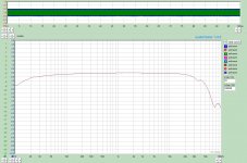
The measurement (1V, 700R generator impedance) not bad, but HF rolloff is stronger than in datasheet (first pic: -1dB: 7Hz..54kHz, about 0.5dB dip at about 34kHz).
The power bandwidth is suitable:
at 10W/8R -second picture-
-1dB: 25Hz..32kHZ
-3dB: 13Hz...54kHz
It looks good. With such a small core you can't have 10W @20Hz, high inductance and low copper loss at the same time. If it had lower loss it could not withstand 10W so low in frequency. From the point of view of a manufacturer the higher loss with all other things in good shape is a more convenient choice because he doesn't need to make several 5K OT's with different power ratings and if he does there is still the great advantage of good performance at convenient price. If he made a 5W with lower loss on this core and a 10W with lower loss on a bigger core you would have no choice for a 300B amp but the bigger one.
However I don't see a dip in the frequency response. That would actually be the start of the roll-off. I see the transformer resonance peak at 40KHz. If the peak were completely damped the roll-off would be gentler and -1 dB point would happen a bit lower in frequency.
Some years ago I built for my friend one A2 capable 300B SE with 5k/10W OPT (he bought this from Transcendar directly).
This transformer is well built one, but both (primary and secondary) DCR is on the high side (381R/0.85R), so copper losses are significant.
For enough headroom I lifted B+ to 440V.
The amp (gyrator loaded C3g, powerdrive, fix bias 300B) capable 10W, the sound is very attractive and powerfull (within its limits).
Measurement:
The manufacturer's frequency response promise is very optimistic -as usual-.
The measurement (1V, 700R generator impedance) not bad, but HF rolloff is stronger than in datasheet (first pic: -1dB: 7Hz..54kHz, about 0.5dB dip at about 34kHz).
The power bandwidth is suitable:
at 10W/8R -second picture-
-1dB: 25Hz..32kHZ
-3dB: 13Hz...54kHz
I think that Transcendar is quite close in their specs, Note that they measure freq response at 1 watt not at full rated power:
5 K to 8 Ohms
Frequency Response: 20 Hz to 90 kHz +/- 1 dB @ 1 Watt
Maximum DC Bias Current: 90 mA
Primary DC Resistance: 370 ohms
Primary Inductance: 40 H @ 120 Hz
Part Number: TT-012-OT
$75.00 each
And for the price it seems more than reasonable.
Note that they measure freq response at 1 watt not at full rated power:
.
There are two pictures:
the one on the left is the FR @1W, the one on the right is the power response.
The high frequency response is the only thing out of spec. The low frequency response with 20Hz @-1dB is correct because it is referred to a source impedance of 5K (i.e. equal to the primary impedance) that is customary when the transformer is not specific to any device.
So in the end 90 mA is the max recommended operative DC current and NOT the saturation current. Q.E.D.
I am looking for the DC current that allows for the greatest symmetrical AC current swing.
The goal is to select an idle current that allows the most symmetrical AC current swing with the least transformer induced distortion at the output.
The question is; how does the specified 90ma maximum bias current address optimizing the performance of this Transendar SET transformer?
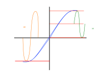
You are asking too much for a transformer, to achieve your goal you need an hysteresis free core, otherwise, even with an almost perfect sinusoidal voltage, AC current in general will be asymmetrical, fortunately, for SE OPT you can approach reasonably to your goal, see the last picture
Tube Output Transformer Concept / Pictures | TTRadio
After thinking for a while (I think slowly) for a given transformer that you can't modify, you only can play with idle current.
i) DC bias current requires an air gap on the core, this makes its magnetic permeability quite constant, which in turn allows a more linear hysteresis loop.
ii) In a SE transformer, primary current flows always in the same direction and DC bias current maintains the core with a certain magnetization all the time, this allows no zero crossing distortion and magnetic domains are pre-aligned, which in turns reduces the work made by the magnetic field Bac, in other words it reduces core losses.
The area inside the hysteresis loop represents core losses, then, your goal is to reduce core losses for the best possible linearity, the only way you have to reduce core losses is maximizing DC bias current and cross your fingers that your transformer is well designed, there is a delicate equilibrium between Bac and Bdc.
Even better, optimize your amplifier, surely it will produce more distortion than the OPT, just be careful to not exceed 90 mA of DC bias current.
You can always adjust the gap...
You would fist need to measure and characterize the transformer...then you can adjust the gap if need be to optimize it for your situation...
Many transformer makers use the same transformer and just adjust the gap to increase their product line ...
You would fist need to measure and characterize the transformer...then you can adjust the gap if need be to optimize it for your situation...
Many transformer makers use the same transformer and just adjust the gap to increase their product line ...
The area inside the hysteresis loop represents core losses, then, your goal is to reduce core losses for the best possible linearity,
In what way is hysteresis related to linearity?
All good fortune,
Chris
Frequency Response: 20 Hz to 90 kHz +/- 1 dB @ 1 Watt
1W measured curve -300B tube at 70mA-.
Attachments
After your words i dislike pp even more
In PP OPT, primary current flows in opposite directions, the core must be "magnetized" cycle by cycle and this produces zero crossing distortion, magnetic domains must be "realigned" cycle by cycle which increase the work done by the external magnetic field, which in turn increases core losses, then linearity is reduced.
In what way is hysteresis related to linearity?
All good fortune,
Chris
Linearity means that voltage and current are related as
V = a I + b, a=constant, b=constant
For an homogeneous and isotropic medium, like a perfect resistor, this yields Ohm's law.
If the medium has hysteresis, like a transformer core, that medium must be anisotropic and nonlinear, then V and I cannot be related by a linear function.
V = V(B), I = I (H), B = μ H
If the medium is anisotropic and nonlinear, i.e. the medium has hysteresis, μ must be a tensor.
hysteresis
popilin,
You made me do it.
You completely missed my question. Too much theory makes heads spin, plus you completely missed the point.
Chris,
With AC only (no DC bias) the hysteresis loop (curve) is sigmoid in shape, fairly linear in the center with decreasing permeability causing a knee and shoulder at the tails. Hopefully a Single End transformer does not have a zero crossing.
The Lesson of the Sigmoid Curve
https://en.wikipedia.org/wiki/Sigmoid_function
Put all the engineering variables, including ‘core losses’, in a bowl and stir them up there is a sweet spot to set the DC bias.
This is my point: Does the 90ma max bias have anything to with the sweet spot or is it like a box of chocolates “you get what you get” Forest Gump?
Take a look at this Lundahl transformer specification.
http://www.lundahl.se/wp-content/uploads/datasheets/1663.pdf
You can buy it gapped for 100ma, 50ma or custom gaps in between. There is also a stated max winding current of 160ma. $150.00
DT
By reputation Transendar is a very good transformer for the money. $75.00.
The sweet spot must be an empirical thing. I will test this thing and report back.
In what way is hysteresis related to linearity?
All good fortune,
Chris
popilin,
You made me do it.
You completely missed my question. Too much theory makes heads spin, plus you completely missed the point.
Chris,
With AC only (no DC bias) the hysteresis loop (curve) is sigmoid in shape, fairly linear in the center with decreasing permeability causing a knee and shoulder at the tails. Hopefully a Single End transformer does not have a zero crossing.
The Lesson of the Sigmoid Curve
https://en.wikipedia.org/wiki/Sigmoid_function
Put all the engineering variables, including ‘core losses’, in a bowl and stir them up there is a sweet spot to set the DC bias.
This is my point: Does the 90ma max bias have anything to with the sweet spot or is it like a box of chocolates “you get what you get” Forest Gump?
Take a look at this Lundahl transformer specification.
http://www.lundahl.se/wp-content/uploads/datasheets/1663.pdf
You can buy it gapped for 100ma, 50ma or custom gaps in between. There is also a stated max winding current of 160ma. $150.00
DT
By reputation Transendar is a very good transformer for the money. $75.00.
The sweet spot must be an empirical thing. I will test this thing and report back.
Last edited:
understanding this correctly ? 0,9T center; top 1,6T bottom 0,2T ???lundahl said:For the S.E. versions of the LL1660, the core air gap is chosen such that the denoted DC current (18mA for a
LL1660/18mA) generates a no signal core flux density of 0.9 Tesla when used with all primaries in series. This
leaves a flux density swing of 0.7 T for the signal
afaik 1,6t is commonly used max for g.o.s.s.
the correct size bucket
Hello,
Yesterday I emailed with Grey at Transendar. Grey tells me that the 90 ma maximum bias current is at both the limit of transformer temperature rise and the limit of saturation. My takeaway is not to push the 90ma limit.
Last night I sat down with a calculator, the back of an envelope and a pencil to see what the size the bucket is.
This transformer is a nominal 10 watts into an 8 ohm load. Doing the maths, watts = I^2 * R. There are ~ 1.12 AC amps on the secondary. There are ~ 0.045 AC amps on the primary.
Leaving equal wiggle room at both ends of the primary AC swing places the idle current at 76.6ma.
The bucket appears to be about the correct size for the gold that I intend to carry.
DT
Yesterday I emailed with Grey at Transendar. Grey tells me that the 90 ma maximum bias current is at both the limit of transformer temperature rise and the limit of saturation. My takeaway is not to push the 90ma limit.
Tell Grey that they are stingy using very thin wire and poor lamination.
Leaving equal wiggle room at both ends of the primary AC swing places the idle current at 76.6ma.
You are putting the cart before the horse, magic numbers will not give better results, just optimize the output stage, if optimum DC bias current exceeds 90 mA, just use another transformer.
I've had thoughts of somehow applying a permanent magnet to the core, to conteract against the single ended idle current's magnet field. To make it seem like a P-P transformer. I can't really picture where to put this magnet (at the lam gaps?), assuming that this idea has any merit at all...
is there a sweet spot
Popilin,
We are not speaking of horses or carts nor are we speaking of a specific amplifier design.
I hear you saying to design the output stage first. If I may, I am thinking of the output transformer first and going back the other direction. Why, because that is a good place to start. Is that the best place to start? Don’t know, don’t care.
Starting with a specific transformer, because it is sitting in front of me, generalizing to the entire choice of Single End Transformers over-all, call it induction.
Now back to the overall question presented; is there a sweet spot to place the bias current?
So far I have come to the conclusion that if we are trying to maximize the power output, no there is not a sweet spot. The required AC swing occupies very much of the available space on the magnetization curve.
DT
You are putting the cart before the horse, magic numbers will not give better results, just optimize the output stage, if optimum DC bias current exceeds 90 mA, just use another transformer.
Popilin,
We are not speaking of horses or carts nor are we speaking of a specific amplifier design.
I hear you saying to design the output stage first. If I may, I am thinking of the output transformer first and going back the other direction. Why, because that is a good place to start. Is that the best place to start? Don’t know, don’t care.
Starting with a specific transformer, because it is sitting in front of me, generalizing to the entire choice of Single End Transformers over-all, call it induction.
Now back to the overall question presented; is there a sweet spot to place the bias current?
So far I have come to the conclusion that if we are trying to maximize the power output, no there is not a sweet spot. The required AC swing occupies very much of the available space on the magnetization curve.
DT
Linearity means that voltage and current are related as
V = a I + b, a=constant, b=constant
Well, not really.
Chris
Chris,
With AC only (no DC bias) the hysteresis loop (curve) is sigmoid in shape, fairly linear in the center with decreasing permeability causing a knee and shoulder at the tails. Hopefully a Single End transformer does not have a zero crossing.
The Lesson of the Sigmoid Curve
https://en.wikipedia.org/wiki/Sigmoid_function
This is a poor description of the hysteresis of the B/H magnetization curve. It also overlooks the main reason to build single-ended amplifiers with output transformers, the changing slope of the curve through zero axis (permeability).
My question about the link between hysteresis and linearity remains.
All good fortune,
Chris
- Status
- This old topic is closed. If you want to reopen this topic, contact a moderator using the "Report Post" button.
- Home
- Amplifiers
- Tubes / Valves
- Single End Transfomers, The hysteresis loop and maximum current