No I mean realizing that a stock product might suck and a mod might clean it up.
I think we all agree with that, but the key word in that sentence is "might". Just randomly changing components won't get you there unless you understand what specific aspects you are trying to improve, and why.
Well Baka did it more the empirical way and the results "got him there", satisfied him; nothing wrong with that.
When you prefer to follow a more scientific approach you will have to walk a much longer road, including physical measurements, psychological factors, DBT and so on, and then there is big chance you will not be able to declare "why you got there...".
When you prefer to follow a more scientific approach you will have to walk a much longer road, including physical measurements, psychological factors, DBT and so on, and then there is big chance you will not be able to declare "why you got there...".
-Any module from Hypex can be discussed here, plus PSU's and ...
Well Baka did it more the empirical way and the results "got him there", satisfied him; nothing wrong with that..
Nothing at all wrong with Baka being happy. There is however an issue with him saying 'it's better/more tranparent/veils lifted/wife in kitchen etc'. Only known is that he is happy with the mods. Nothing else can be inferred.
There is no issue: Baka made sufficiently clear that he found the modifications to be a worthwile improvement to the sound. He did not claim to have a less distorting and therefore better sounding amp after the mod. It's all subjective.
He did claim actual differences. See below various audiophile works like 'grain/transparency/speed/dynamics'. He did not claim less distortion, but did claim better sound.
As for the opamp the important issue here is an input bias current that should be relatively low. That narrows the possible choices. According to the datasheet LM49722 is a "directly interchangeable with LME49720, LM4562
and LME49860 for similar operating voltages". Specs are almost the same but the later one sounds audibly better. It is at least more transaparent and well suited for that position.
All smd resistor around the opamp are the magnetic ones. The same goes for the couple of Vishay MELF resistors used there. Susumu resistors are at least non magnetic and the end result was a perceivable cleaner sound. These resistors are, for example, used in SE editon of DEXA Technologies Discrete Audio Op-Amp. I am sourcing my experience from these opamps having them both in standard and se edition.
Changing the ordinary polyester capacitor for the polypropylene one in the output filter does produce less grain, better speed, dynamics and resolution. That should be of no surprise. Wima is particulary good beeing also very compact - radial leads with 5mm spacing.
Well Baka did it more the empirical way and the results "got him there", satisfied him; nothing wrong with that.
"Empirical" is actually a big word to use. Here is Adriaan de Groot's famous picture of the empirical cycle:

A bit more than just "let's try changing something and see how it sounds".
But yes, Baka did something that satisfied him. Unfortunately it is probably not very useful for anyone else. It doesn't need to be (this is DIY after all), but I also don't see anything wrong in pointing out the shortcomings in his approach. Shouldn't both sides of the coin be presented? Peer review, verification and criticism are some of the most important mechanisms in science and engineering.
What's your problem SGK?
No problem. I just find it humorous when someone swaps out resistors because 'they're magnetic' yet doesn't know what model the resistors being removed are and then selects a replacement that isn't non-magnetic. At a minimum one would have thought - given his desire to use non-magnetic parts ... for whatever reason - he'd have a look at his favourite manufacturer's range and select a part from their non-magnetic series. I just think it is indicative of the level of professionalism involved. But hey, it's his dime.
Last edited:
New NC400 stereo build - questions about DC offset
Hi all,
I started reading up on this thread some 9 months ago and have read, well, almost everything until I took the plunge and got a complete kit last november which I finished building just before x-mas.
For your entertainment I have attached a couple of pics. I am using 2 x NC400 combined with the SMPS1200A400. The DC-input and switch on the back left are for SMPS standby which I yet have to finish (hence a couple of remaining loose wires).
front
back
inside
reading
input
system
When I finished the basic build last december I took some quick readings on the outputs which were showing considerable DC-offset, but other than that the unit worked fine and since then has performed many hours up to my satisfaction.
Finally yesterday my own multimeter arrived so I immediately opened up the unit and again took some readings as follows (if anyone has questions about these let me know):
These readings were done after some 10-minute warm up time with the top cover off (unit still fairly cool although it never really runs hot).
Following the Hypex info which I found here, I connected nAmpon to "Auto Amplifier Enable" on the SMPS, assuming this automatically unmutes the modules thus fully taking advantage of the SMPS soft start feature.
Would DC offset be further reduced/eliminated if I connected nAmpon directly to XLR ground (same as where shielding currently is connected together with XLR pin 1). BTW I did verify that XLR ground connects to chassis.
Apart from DC, any other comments on this build?
As for my listening experience. I am using the amp to drive a pair of Tannoy D700's and it is quite an improvement over any amp I have had before (which isn't much; some Denon stereo and surround amps, as well as a Bewitch 2A3 tube amp). They also clearly sounded more detailed, defined than my brother's Parasound 2200 on the same speakers.
Hi all,
I started reading up on this thread some 9 months ago and have read, well, almost everything until I took the plunge and got a complete kit last november which I finished building just before x-mas.
For your entertainment I have attached a couple of pics. I am using 2 x NC400 combined with the SMPS1200A400. The DC-input and switch on the back left are for SMPS standby which I yet have to finish (hence a couple of remaining loose wires).
front
An externally hosted image should be here but it was not working when we last tested it.
back
An externally hosted image should be here but it was not working when we last tested it.
inside
An externally hosted image should be here but it was not working when we last tested it.
reading
An externally hosted image should be here but it was not working when we last tested it.
input
An externally hosted image should be here but it was not working when we last tested it.
system
An externally hosted image should be here but it was not working when we last tested it.
When I finished the basic build last december I took some quick readings on the outputs which were showing considerable DC-offset, but other than that the unit worked fine and since then has performed many hours up to my satisfaction.
Finally yesterday my own multimeter arrived so I immediately opened up the unit and again took some readings as follows (if anyone has questions about these let me know):
- unit as-is (no external connections): L -20mV, R -22mV
- with nAmpon disconnected: L +173mV, R +225mV
- nAmpon + XLR's disconnected from module: L +152mV, R +235mV
These readings were done after some 10-minute warm up time with the top cover off (unit still fairly cool although it never really runs hot).
- First of all, do these readings make sense?
- Is it normal to have so much DC-offset when nAmpon and/or XLR inputs are disconnected?
- Why are the first readings negative? Or does + vs. - not matter in this case?
- What would be ideal? Just a few mV above 0?
Following the Hypex info which I found here, I connected nAmpon to "Auto Amplifier Enable" on the SMPS, assuming this automatically unmutes the modules thus fully taking advantage of the SMPS soft start feature.
Would DC offset be further reduced/eliminated if I connected nAmpon directly to XLR ground (same as where shielding currently is connected together with XLR pin 1). BTW I did verify that XLR ground connects to chassis.
Apart from DC, any other comments on this build?
As for my listening experience. I am using the amp to drive a pair of Tannoy D700's and it is quite an improvement over any amp I have had before (which isn't much; some Denon stereo and surround amps, as well as a Bewitch 2A3 tube amp). They also clearly sounded more detailed, defined than my brother's Parasound 2200 on the same speakers.
Last edited:
First of all, do these readings make sense?
As badman pointed out, the offset doesn't matter with an open output - the offset with a load connected is the interesting one to measure.
Polarity doesn't matter / is irrelevant.Why are the first readings negative? Or does + vs. - not matter in this case?
Rather unlikely. nAmpon is a switching input - it is either off or on.Would DC offset be further reduced/eliminated if I connected nAmpon directly to XLR ground (same as where shielding currently is connected together with XLR pin 1).
Hi all,
I started reading up on this thread some 9 months ago and have read, well, almost everything until I took the plunge and got a complete kit last november which I finished building just before x-mas.
For your entertainment I have attached a couple of pics. I am using 2 x NC400 combined with the SMPS1200A400. The DC-input and switch on the back left are for SMPS standby which I yet have to finish (hence a couple of remaining loose wires).
front
An externally hosted image should be here but it was not working when we last tested it.
back
An externally hosted image should be here but it was not working when we last tested it.
inside
An externally hosted image should be here but it was not working when we last tested it.
reading
An externally hosted image should be here but it was not working when we last tested it.
input
An externally hosted image should be here but it was not working when we last tested it.
system
An externally hosted image should be here but it was not working when we last tested it.
When I finished the basic build last december I took some quick readings on the outputs which were showing considerable DC-offset, but other than that the unit worked fine and since then has performed many hours up to my satisfaction.
Finally yesterday my own multimeter arrived so I immediately opened up the unit and again took some readings as follows (if anyone has questions about these let me know):
- unit as-is (no external connections): L -20mV, R -22mV
- with nAmpon disconnected: L +173mV, R +225mV
- nAmpon + XLR's disconnected from module: L +152mV, R +235mV
These readings were done after some 10-minute warm up time with the top cover off (unit still fairly cool although it never really runs hot).
- First of all, do these readings make sense?
- Is it normal to have so much DC-offset when nAmpon and/or XLR inputs are disconnected?
- Why are the first readings negative? Or does + vs. - not matter in this case?
- What would be ideal? Just a few mV above 0?
Following the Hypex info which I found here, I connected nAmpon to "Auto Amplifier Enable" on the SMPS, assuming this automatically unmutes the modules thus fully taking advantage of the SMPS soft start feature.
Would DC offset be further reduced/eliminated if I connected nAmpon directly to XLR ground (same as where shielding currently is connected together with XLR pin 1). BTW I did verify that XLR ground connects to chassis.
Apart from DC, any other comments on this build?
As for my listening experience. I am using the amp to drive a pair of Tannoy D700's and it is quite an improvement over any amp I have had before (which isn't much; some Denon stereo and surround amps, as well as a Bewitch 2A3 tube amp). They also clearly sounded more detailed, defined than my brother's Parasound 2200 on the same speakers.
Nice work.
Which enclosures are those?
Possible wiring guide revision
Glad you found the wiring diagram they sent useful, however I now think it might not be 100% correct for use with NC400s which contain HxR voltage regulators.
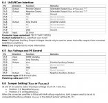
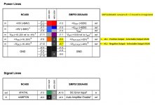
After re-re-reading the SMPS1200 manual, it looks like jumpers J6 + J7 should be changed to the "unregulated" position and that J4.1 and J4.2 should be used instead of J5.3 and J5.7 for +Vsig and -Vsig. The manual specifies J4 as the "UcD/NCore Interface" and J5 as "Aux Voltage".
I haven't actually made any changes yet and am curious what others think. I've reached out to Hypex support to confirm and will update the post once they reply.
EDIT - Looks like J5.3 is also Vaux. Perhaps they can be used interchangeably depending on the jumper.
Following the Hypex info which I found here, I connected nAmpon to "Auto Amplifier Enable" on the SMPS, assuming this automatically unmutes the modules thus fully taking advantage of the SMPS soft start feature.
Glad you found the wiring diagram they sent useful, however I now think it might not be 100% correct for use with NC400s which contain HxR voltage regulators.
After re-re-reading the SMPS1200 manual, it looks like jumpers J6 + J7 should be changed to the "unregulated" position and that J4.1 and J4.2 should be used instead of J5.3 and J5.7 for +Vsig and -Vsig. The manual specifies J4 as the "UcD/NCore Interface" and J5 as "Aux Voltage".
I haven't actually made any changes yet and am curious what others think. I've reached out to Hypex support to confirm and will update the post once they reply.
EDIT - Looks like J5.3 is also Vaux. Perhaps they can be used interchangeably depending on the jumper.
Attachments
Last edited:
After re-re-reading the SMPS1200 manual, it looks like jumpers J6 + J7 should be changed to the "unregulated" position and that J4.1 and J4.2 should be used instead of J5.3 and J5.7 for +Vsig and -Vsig. The manual specifies J4 as the "UcD/NCore Interface" and J5 as "Aux Voltage".
You want to use the on-board regulators of the nc400's, so yes, the SMPS1200 should be set to "unregulated". As far as I understand (don't have a SMPS1200 handy to verify) J4.1/4.2 and J5.3/5.7 are connected to the same aux feed, so it doesn't matter which one you use - it only matters from a connector/cable loom point of view.
Hello Esteemed nCorette Smokers ")
This talk of bypassing the Buffer on the nc500 ...yes I am aware the Source needs some serious balls to drive it as Bavmike says, but if my Source is on max and it delivers medium volume this test will suffice
...am curious if NO BUFFER will sound any different ;-)
Thanks for the pointers or dubious comments on how to do this, please
Last edited:
You can try adjusting the DC offset of the modules if you have a multimeter.
The procedure is as follows.
Power up the module. Leave both input and output unconnected.
First, adjust R95 to 0 while measuring between non-inverted input and ground.
Then, with nothing attached to input but with the amp enabled, adjust R136 close to 0 while measuring on the output.
The procedure is as follows.
Power up the module. Leave both input and output unconnected.
First, adjust R95 to 0 while measuring between non-inverted input and ground.
Then, with nothing attached to input but with the amp enabled, adjust R136 close to 0 while measuring on the output.
Last edited:
@Julf
-- Thanks for the feedback on the SMPS1200 connections. Will look in to it further once I'm ready to redo the wiring layout.
Here's a thought...
Could one completely eliminate the XLR jack from the NCore enclosure?
Curious if one could rig up a short (1-2m) interconnect direct to NC400, 2x2 Microfit to XLR plug. It seems that with proper cable strain relief and Pin 1 to ground on both chassis it might be a possibility.
- Status
- Not open for further replies.
- Home
- Amplifiers
- Class D
- Hypex Ncore