Correct, TI has habit of not changing datasheet, they answered questions about it on their forum and I believe they answered they had no idea how 5k6 got in the datasheet. Synch capacitor mistake was promissed 3 years ago to be fixed in next datasheet update, but still there after all revisions ")
OK.....is 47 kOhm not a bit much compared to the 5k6 . What value did they mean then ?
* What sync capacitor mistake ? You are deep into these chips it seems
Edit: just found the info on their forum. Still they mix up R1 and R2 in that post ?! Anyway the value of the resistor to GND is not important when no divider is used. It serves just to pull the pin to GND in that case.
* What sync capacitor mistake ? You are deep into these chips it seems
Edit: just found the info on their forum. Still they mix up R1 and R2 in that post ?! Anyway the value of the resistor to GND is not important when no divider is used. It serves just to pull the pin to GND in that case.
Last edited:
Here is one:
TPA3116/TPA3118/TPA3130 Gain Setting in Master and Slave
Prodigy 100 points
John Guy1
John Guy1
Hi
Attempting to set 20dB gain on a TPA3118, and I believe there is an inconsistency in the datasheet.
•In the EC table, it says for GAIN(BTL) mode, for 20dB, connect R2 of 20k to ground, R1 open.
•In table 1, it says for GAIN(MSTR) mode for 20dB, connect R2 of 5.6k to grounb, R1 open.
I believe there is a typo in EC table, it is master, not BTL mode (always BTL mode, that is)
For a gain of 20dB, what is the correct value for R2?
Thanks
John
Prodigy 100 points
John Guy1
John Guy1
Apr 4, 2013 5:33 PM
Reply
1 Reply
Guru 166460 points
Don Dapkus
Don Dapkus
Apr 5, 2013 3:28 AM
Hi, John,
Nice catch, I thought we fixed that... It doesn't really matter the value of R2 in this case. The most important thing is if you use a divider, you don't draw too much current out of GVDD... Since in this case, no current is drawn from GVDD, you just want something to pull the pin to ground.
And, yes, it should be MSTR, not BTL...
I will get the d/s updated the next go-around.
-d2
-----
Don Dapkus
Audio Applications Engineering Manager
Dallas, TX USA
For synch there are multiple times people asked and got answered, TI-EVM values are advised, they rediscover the error in datasheet over and over again LOL
edit: ok you saw post already We read from left to right and left resistor is r2 and right resistor is r1, to make it easy to mistake
TPA3116/TPA3118/TPA3130 Gain Setting in Master and Slave
Prodigy 100 points
John Guy1
John Guy1
Hi
Attempting to set 20dB gain on a TPA3118, and I believe there is an inconsistency in the datasheet.
•In the EC table, it says for GAIN(BTL) mode, for 20dB, connect R2 of 20k to ground, R1 open.
•In table 1, it says for GAIN(MSTR) mode for 20dB, connect R2 of 5.6k to grounb, R1 open.
I believe there is a typo in EC table, it is master, not BTL mode (always BTL mode, that is)
For a gain of 20dB, what is the correct value for R2?
Thanks
John
Prodigy 100 points
John Guy1
John Guy1
Apr 4, 2013 5:33 PM
Reply
1 Reply
Guru 166460 points
Don Dapkus
Don Dapkus
Apr 5, 2013 3:28 AM
Hi, John,
Nice catch, I thought we fixed that... It doesn't really matter the value of R2 in this case. The most important thing is if you use a divider, you don't draw too much current out of GVDD... Since in this case, no current is drawn from GVDD, you just want something to pull the pin to ground.
And, yes, it should be MSTR, not BTL...
I will get the d/s updated the next go-around.
-d2
-----
Don Dapkus
Audio Applications Engineering Manager
Dallas, TX USA
For synch there are multiple times people asked and got answered, TI-EVM values are advised, they rediscover the error in datasheet over and over again LOL
edit: ok you saw post already
We read from left to right and left resistor is r2 and right resistor is r1, to make it easy to mistake
Last edited:
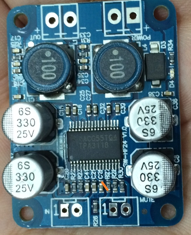
Can someone post which Rxx designation on the Sanwu 3118 PBTL the above TI "R1" and "R2" correspond to? The spec sheet says R1 goes to pin 8 and R2 goes to pin 7. But the lines are very tight and I can't tell. I am guessing it is R27 and R28 on Sanwu?
TI sheet:
Ok, a few minutes with magnifier and probe indicates R27 on Sanwu is connected to pin 7 and 8, and R28 on Sanwu is connected to pin 8. Thus R2(TI) is R27 and R1(TI) is R28.
My latest two boards have R2=753 (7.5kohm) and R1=473 (4.7kohm) or 36dB.
TI sheet:
An externally hosted image should be here but it was not working when we last tested it.
Ok, a few minutes with magnifier and probe indicates R27 on Sanwu is connected to pin 7 and 8, and R28 on Sanwu is connected to pin 8. Thus R2(TI) is R27 and R1(TI) is R28.
My latest two boards have R2=753 (7.5kohm) and R1=473 (4.7kohm) or 36dB.
Last edited:
Four (eight?) different sonic signatures available too. I suppose that the hissing selection (36db) isn't valid, so, just 3 then.
20db, 26db, 32db gain settings could make your amp sound different.
Also, 60k, 30k, 15k loads could make your source sound different.
It is valid, just logically higher noisefloor and inputimpedance could create some problems.
Ok, a few minutes with magnifier and probe indicates R27 on Sanwu is connected to pin 7 and 8, and R28 on Sanwu is connected to pin 8. Thus R2(TI) is R27 and R1(TI) is R28.
My latest two boards have R2=753 (7.5kohm) and R1=473 (4.7kohm) or 36dB.
What were the resistor values used on the Sanwu that had 32db setting?
I'm probably going to need that.
What were the resistor values used on the Sanwu that had 32db setting?
39k [393] & 100k [104] ... on both boards that I have, purchased at the same time
j.R.c
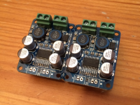
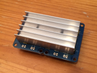
I am putting together my next Sanwu 3118 PBTL. This one is a little stereo amp I am making for a friend. It's got a small heatsink glued to the bottom (took it from a $5 TDA7294). This one has the 36dB gain and I am thinking that is too much and should swap out resistors for maybe 26dB? I added some nice terminal blocks (spacing on pin had to be manually adjusted just a bit smaller from standard 5mm pitch.
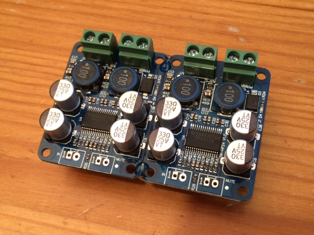

Attachments
What were the resistor values used on the Sanwu that had 32db setting?
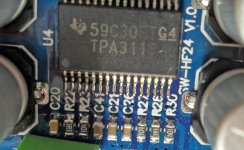
Pic of one of the two 32dB boards with the resistors very clear:
Attachments
Change them to 20 dB and your troubles are over. Just remove the resistor on each board. That way they'll be 60 kOhm each so 30 kOhm in parallel.
Remove R28 (4.7 ohm)?
- Home
- Amplifiers
- Class D
- Cheap TPA3118D2 boards, modding them and everything that comes with it