I would like a model for the 6AC7 if anyone has one. Many thanks.
I did eventually find a 6AC7 somewhere on the net, by Steve Bench. I have not verified its accuracy. I did use it for a couple of sims and I noticed a higher noise floor and lots of odd order harmonics going well up into Mhz range, when compared to other tubes in the same circuit. Both in pentode and triode. Not sure that's due to the model or the tube characteristics.
.SUBCKT 6AC7 1 4 2 3
+ PARAMS: MU=49.9 EX=1.47 KG1=435 KP=162 KVB=12.3 ; KG2=415
+ CCG=11P CPG1=.015P CCP=5P RGI=2K
RE1 7 0 1MEG ; DUMMY SO NODE 7 HAS 2 CONNECTIONS
E1 7 0 VALUE= ; E1 BREAKS UP LONG EQUATION FOR G1.
+{V(4,3)/KP*LOG(1+EXP((1/MU+V(2,3)/V(4,3))*KP))}
G1 1 3 VALUE={(PWR(V(7),EX)+PWRS(V(7),EX))/KG1*ATAN(V(1,3)/KVB)}
*G2 4 3 VALUE={(EXP(EX*(LOG((V(4,3)/MU)+V(2,3)))))/KG2}
g2 4 3 value= {(I(G1)*100/(V(1,3) + 100))} ; models change in current with change in plate
RCP 1 3 1G ; FOR CONVERGENCE
C1 2 3 {CCG} ; CATHODE-GRID 1
C2 1 2 {CPG1} ; GRID 1-PLATE
C3 1 3 {CCP} ; CATHODE-PLATE
R1 2 5 {RGI} ; FOR GRID CURRENT
D3 5 3 DX ; FOR GRID CURRENT
.MODEL DX D(IS=1N RS=1 CJO=10PF TT=1N)
.ENDS
PM meYes , who is willing to utrace it for me?
Best regards
Balle
I don't have it coded into a Spice model yet. However, it should be straightforward to take the above formulas and create the Spice model.
Perhaps this should work -- the tube is 6AT6
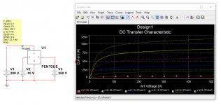
.subckt PENTODE 1 2 3 4
+params: KG1=0.003751 kp1=-2.491 kp2=3.935 kp3=3.716e-5 kp4=0.1675 kt1=29 kt2=0.2549 kc1=7.829e-4 kc2=6.068e-2 kc3=1.098 ks1=-3.567e-6 ks2=3.267e-3 ks3=-1.38e-2 kcs=0.09196 ecref=0 esref=250
E1 7 0 Value = (V(1,4))
E2 8 0 Value = (V(3,4))
E3 9 0 Value = (V(2,4))
RE1 7 0 1e12
G1 1 4 VALUE =(KG1*V(7)+((kp1/(kp2+v(7))+(kp3*v(7))+kp4)-KG1*V(7))/(1+EXP((KT1-V(7))*KT2)))*((kc1*V(8)^2)+kc2*v(8)+kc3)*((ks1*V(9)^2)+ks2*v(9)+ks3)*(1/(1-kcs*(V(8)-ecref)*(1-V(9)/esref)))
RCP 1 4 1e12
C1 2 3 2.4e-12
C2 1 2 3.9e-12
C3 1 3 0.7e-12
R1 2 5 2000
D3 5 3 dx
.model dx d(is=1e-9 rs=1 cjo=10e-12)
Isn't the 6AT6 a triode (+ diodes)?Perhaps this should work -- the tube is 6AT6
Isn't the 6AT6 a triode (+ diodes)?
I'm sorry, yes. It's for the 6V6GT -- I had the 6AT6 on my brain owing to the Webcor guitar amp thread. Will ask the moderator to change it.
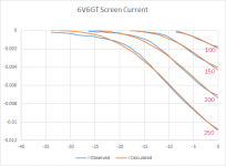
The model is not yet adapted for screen current as Weaver had mentioned. Will work on that next week.

Needed some curly braces in just the right spots.Looking forward to seeing the screen grid current... btw, I could not get the above model to run under LTSpice.
E1, E2, E3, G1 lines.
Code:
.subckt PENT 1 2 3 4
+params: KG1=0.003751 kp1=-2.491 kp2=3.935 kp3=3.716e-5 kp4=0.1675 kt1=29 kt2=0.2549 kc1=7.829e-4 kc2=6.068e-2 kc3=1.098 ks1=-3.567e-6 ks2=3.267e-3 ks3=-1.38e-2 kcs=0.09196 ecref=0 esref=250
E1  7 0 Value={V(1,4)}
E2  8 0 Value={V(3,4)}
E3  9 0 Value={V(2,4)}
RE1 7 0 1e12
G1  1 4 VALUE={(KG1*V(7)+((kp1/(kp2+v(7))+(kp3*v(7))+kp4)-KG1*V(7))/(1+EXP((KT1-V(7))*KT2)))*((kc1*V(8)**2)+kc2*v(8)+kc3)*((ks1*V(9 )**2)+ks2*v(9)+ks3)*(1/(1-kcs*(V(8)-ecref)*(1-V(9)/esref)))}
RCP 1 4 1e12
C1  2 3 2.4e-12
C2  1 2 3.9e-12
C3  1 3 0.7e-12
R1  2 5 2000
D3  5 3 dx
.model dx d(is=1e-9 rs=1 cjo=10e-12)
.ends
Last edited:
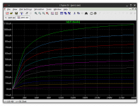
Looking forward to seeing the screen grid current...
So am I, it's giving me a serious headache. Not nearly as straightforward...
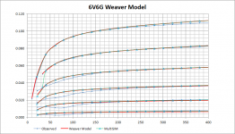
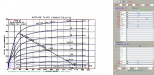
Yup that looks pretty good, did you do an acid-test? Try adding the anode and screen curves together, do they match up with 6V6GT's triode curves?This seems to approximate well:
y = 1.705*w^2 - 0.0011545*w*z - 0.0088955*x*w
where W is the anode current, Z the screen voltage and X the Control Grid Voltage.
 Distortion canceling related posts moved here: http://www.diyaudio.com/forums/tubes-valves/287403-6sn7-distortion-canceling-amp.html#post4626391
 Discussion was out of scope for this thread.
http://www.diyaudio.com/forums/tubes-valves/287403-6sn7-distortion-canceling-amp.html#post4626391
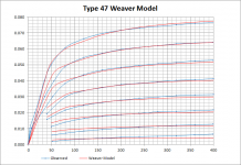
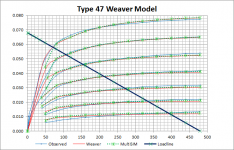
A mediocre type 47 pentode model attached.
If anyone has better model, please inform.
**** 47 ******************************************
* Created on 02/24/2016 15:00 using paint_kip.jar
* Model Paint Tools: Trace Tube Parameters over Plate Curves, Interactively
* Plate Curves image file: 47.jpg
* Data source link: <plate curves URL>
*----------------------------------------------------------------------------------
.SUBCKT PENT_47 1 2 3 4 ; P G K G2
+ PARAMS: CCG=3P CGP=1.4P CCP=1.9P RGI=2000
+ MU=8.6 KG1=2995.6 KP=38.2 KVB=32.6 KVC=1.57 VCT=0.0139 EX=1.3 KG2=0
* Vp_MAX=520 Ip_MAX=80 Vg_step=4 Vg_start=0 Vg_count=8
* Rp=5000 Vg_ac=15.3 P_max=7.5 Vg_qui=-15.3 Vp_qui=250 UL=0.43 EG2=240
* X_MIN=182 Y_MIN=191 X_SIZE=782 Y_SIZE=480 FSZ_X=1616 FSZ_Y=876 XYGrid=false
* showLoadLine=n showIp=y isDHP=n isPP=n isAsymPP=n isUL=n showDissipLimit=n
* showIg1=n gridLevel2=n isInputSnapped=n
* XYProjections=n harmonicPlot=y harmonics=y
*----------------------------------------------------------------------------------
RE1 7 0 1G ; DUMMY SO NODE 7 HAS 2 CONNECTIONS
E1 7 0 VALUE= ; E1 BREAKS UP LONG EQUATION FOR G1.
+{V(4,3)/KP*LOG(1+EXP((1/MU+(VCT+V(2,3))/V(4,3))*KP))}
G1 1 3 VALUE={(PWR(V(7),EX)+PWRS(V(7),EX))/KG1*ATAN(V(1,3)/KVB)}
* Alexander Gurskii screen current, see audioXpress 2/2011
RE2 8 3 1G ; Dummy
G2 8 3 VALUE={(PWR(V(7),EX)+PWRS(V(7),EX))/KG2*(KVC-ATAN(V(1,3)/KVB))}
E2 8 4 VALUE={0} ; Dummy
RCP 1 3 1G ; FOR CONVERGENCE
C1 2 3 {CCG} ; CATHODE-GRID 1
C2 1 2 {CGP} ; GRID 1-PLATE
C3 1 3 {CCP} ; CATHODE-PLATE
R1 2 5 {RGI} ; FOR GRID CURRENT
D3 5 3 DX ; FOR GRID CURRENT
.MODEL DX D(IS=1N RS=1 CJO=10PF TT=1N)
.ENDS
*$
Attachments
- Home
- Amplifiers
- Tubes / Valves
- Vacuum Tube SPICE Models