I think I have found answer to my question:
"There are those who would correctly point out that you can run lower distortion if you put
some resistance on the Sources of the input Jfets because they would not then be running
near their Idss figure. What happens there is that the Gates can start drawing a little current
on peak inputs. I tried it both ways, and I didn't have any issues either way, so I left those
resistors off. However, if you have Jfets with high Idss values then some resistances on the
Sources would lower the bias current and thus the heat dissipation of these transistors.
In this circuit, the input Jfets were chosen for Idss at 8 mA or so, but you can get them with
Idss up to 20 mA, which times the 23 volt supply will exceed their 0.4 watt rating. Or you
might try some other Jfets with higher Idss or higher supply voltages. If you find that you
need to degenerate the input Jfets with some resistance, you will find that there is little or no
performance penalty for small resistance values."
Last edited:
Am I right, that lm329 has reversed polarity compared to LED?
No more questions now.
Yes.
Dear sir
The cap lead that is soldered to the source of the mosfet needs to be directly connected the wiper of the pot you will be using.
You will have to desolder then resolder for the electrical connection you require.
Thanks, but it was not among the issues.
")
I have other plans for it.
I'm going to cut the copper trace.
Then I will connect the wiper to the appropriate point.
I will fired up it as is, this is my thought, then I will modify it with 10 Ohm pots.
What do you think?
I was quite sure, thanks for the clarification Buzz!
Sounds absolutely fineI'm going to cut the copper trace.
Then I will connect the wiper to the appropriate point.
I will fired up it as is, this is my thought, then I will modify it with 10 Ohm pots.
What do you think?
Last edited:
Yes I know.
Regardles of it, circuit will work with them, isn't it?
Of course settings will be different.
Yes Irfp250 are great devices in this circuit
Last edited:
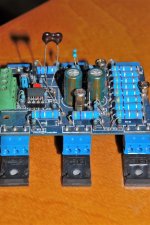
I used formerly this kind of mounting for output FETs:
That's a cool setup for experimentation
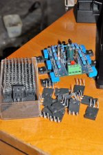
Maybe you have noticed I have drilled out FETs with an M4 drillbit.
Perhaps there are ones here who are despise me because of it.
I must have to say I never ever had any problem with it.
I drilled TO264 packages for my Leach amp also.
It is much easier to make M4 threads than M3.
M3 taps are broken quite easily.
Perhaps there are ones here who are despise me because of it.
I must have to say I never ever had any problem with it.
I drilled TO264 packages for my Leach amp also.
It is much easier to make M4 threads than M3.
M3 taps are broken quite easily.
- Status
- This old topic is closed. If you want to reopen this topic, contact a moderator using the "Report Post" button.
- Home
- Amplifiers
- Pass Labs
- F6 amp with SemiSouth SJEP120R100