I think you're missing a connection at the input.
Check back again. I just fixed the attached image. (Sorry 'bout that!)
--
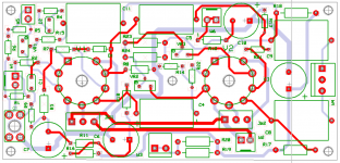
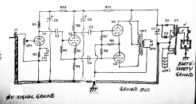
Hi,& Cnpope. I want to share with you an actual practical work experience. This is OTL driver, the thick background track is the signal ground and on the left G1 is the M4 screw nut on pcb and 1 ohm resistor to chassis. The input W1 is near the ground nut. Once the drive is ground lift it makes little difference as where it's connected to chassis, but preferable on same place as power amp. Very little hum is dead quiet, ~1mV for 25W model, I could not barely hear hum from a sensitive headphones. A bigger ground lift can be install on chassis to PE if require to adapt to other preamp. The scheme does make a difference to buzz and hum as learn from practical experiences.
Attachments
Last edited:
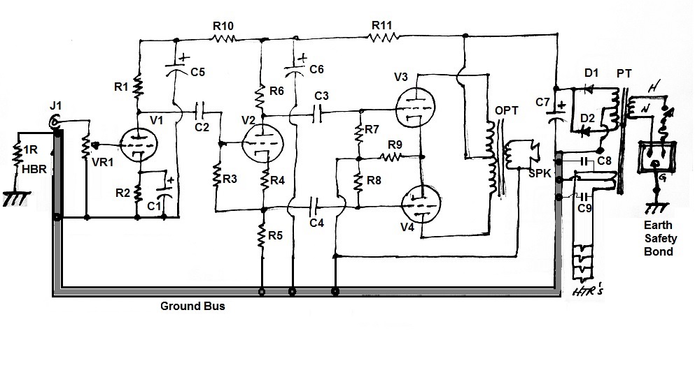
I think I'm following you. Attached is a drawing of what I think you're saying... --
Yes, that's it.
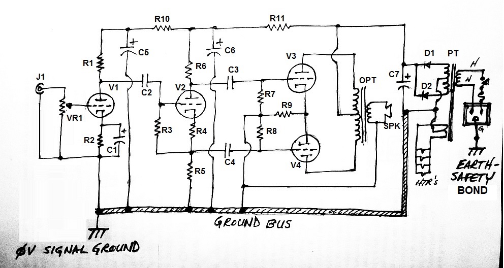
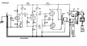
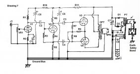
Below, combination of the left of the first image and the right of the second image (as recommended by Sy) should give good results.
Try to get the lowest as possible impedance for the bus ground.
Hi,& Cnpope. I want to share with you an actual practical work experience. This is OTL driver, the thick background is the signal ground and on the left iG1 is the M4 screw nut on pcb and 1 ohm resistor to chassis. The input is near the ground nut. Once the drive is ground lift it makes little difference as where it's connected to chassis, but preferable on same place as power amp. Very little hum is dead quiet, ~1mV for 25W model, I could not barely hear hum from a sensitive headphones. A bigger ground lift can be install on chassis to PE if require to adapt to other preamp. The scheme does make a difference to buzz and hum as learn from practical experiences.
Sorry man. I can't follow you.
No te entiendo. What is 'the thick background'?the thick background is the signal ground
Sorry, you lost me. What is 'the drive'?Once the drive is ground lift it makes little difference as where it's connected to chassis, but preferable on same place as power amp.
What is 'PE'? Why would using a different preamp require a different 'ground lift'? And what is meant by a 'bigger' 'ground lift'?A bigger ground lift can be install on chassis to PE if require to adapt to other preamp.
--
And again, I'm sorry, je ne vous comprends pas.
The second image shows the two separate connections to chassis earth, two separate ground buses. I thought that was a bad thing.
I think you mean the ground wiring for the input stage from the top image. I think...
And I think you mean change the heater wiring to follow SY's suggestions (in the bottom image).
--
forr said:Below, combination of the left of the first image and the right of the second image (as recommended by Sy) should give good results.
Try to get the lowest as possible impedance for the bus ground.
The second image shows the two separate connections to chassis earth, two separate ground buses. I thought that was a bad thing.
I think you mean the ground wiring for the input stage from the top image. I think...
And I think you mean change the heater wiring to follow SY's suggestions (in the bottom image).
--
Last edited:
PE is Physical Earth, "the thick background" the thick background track. Dirver, preamp + driver, Bigger strong bridge to withstand large current for safety.Sorry man. I can't follow you.
No te entiendo. What is 'the thick background'?
Sorry, you lost me. What is 'the drive'?
What is 'PE'? Why would using a different preamp require a different 'ground lift'? And what is meant by a 'bigger' 'ground lift'?
--
Last edited:
That statement conflicts with the solutions that Joffe proposes in his paper. Introducing a 1 to 10 ohm resistor in between the Ground Bus and Chassis does not provide the lowest possible impedance for all frequencies, or at least I think so.forr said:Try to get the lowest as possible impedance for the bus ground.
--
Last edited:
forr said:Try to get the lowest as possible impedance for the bus ground.
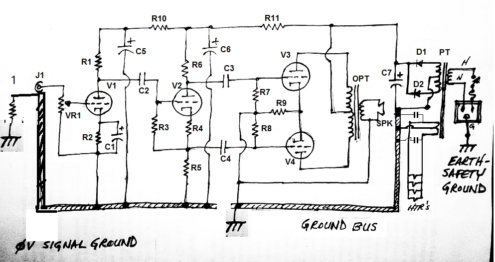
Lowest impedance for bus ground to where? The input stage's -ve? To chassis earth? Which of the two attached drawings accomplishes this better?
(Note that the drawings are identified in the upper left corner)
--
Attachments
Last edited:
Referencing this:
I could change the HBR (1 ohm) to paralleled bunch of two diodes in anti-polarity, 0.01uF 1kV ceramic cap and 1R resistor. That's the best way to do this, correct?
--
I think add a capacitor is like grounding ac signal include hum to chassis directly defeat the purpose of 1 ohm ground lift!! Not for HBR.
There's more than a sticky, there's an actual article. I haven't read this in a while, I hope it doesn't add confusion to the thread:This has already been discussed many times.
If this has been discussed many times, should we not have a sticky for it? Grounding is a safety issue; thus, probably should have a sticky.
http://www.diyaudio.com/forums/diya...udio-component-grounding-interconnection.html
Lowest impedance for bus ground to where? The input stage's -ve? To chassis earth? Which of the two attached drawings accomplishes this better?
(Note that the drawings are identified in the upper left corner)
--
Your two last drawings are quite similar. My prefered one is #6.
I may even use the chassis as the ground bus.
But many people will disagree, there is no consensus about ground schemes and I am not going to claim that I hold the ultimate truth.
In an active control and phone amp I recently built, I played with a piece of wire to introduce various ground loops. I did not succeed to obtain any hum at the output.
It may be time for you to experience now.
Regards.
...Why would using a different preamp require a different 'ground lift'? And what is meant by a 'bigger' 'ground lift'?
--
Because if the preamp is also earthed this creates a ground loop, no? So one of them has to be ground lifted, is better on our side. Bigger means larger current capacity
") Sorry a lot of writings at same time forgive for my freq. errors due to this, let's slow down! Allow 3 mins for checking/editing, don't quote too fast!!
Sorry a lot of writings at same time forgive for my freq. errors due to this, let's slow down! Allow 3 mins for checking/editing, don't quote too fast!!
Last edited:
"I may even use the chassis as the ground bus.
But many people will disagree, there is no consensus about ground schemes and I am not going to claim that I hold the ultimate truth."
In some countries ground lift of any sort is not acceptable, so you have to design one without it. That is good you can do it. Interconnect plays an important part too. maybe all the use of ground lift is get rid of hum introduced by interconnect screen rather than the actual signal ground loop.
There's more than a sticky, there's an actual article. I haven't read this in a while, I hope it doesn't add confusion to the thread:
http://www.diyaudio.com/forums/diya...udio-component-grounding-interconnection.html
That's a good reading. Thanks for the link.
Because if the preamp is also earthed this creates a ground loop, no?
A ground loop is not necessarily harmful.
A ground loop is not necessarily harmful.
Wow, what about portion of signal being send over ground loop, possible? Experienced it!!
Hi,& Cnpope. I want to share with you an actual practical work experience. This is OTL driver, the thick background track is the signal ground and on the left G1 is the M4 screw nut on pcb and 1 ohm resistor to chassis. The input W1 is near the ground nut. Once the drive is ground lift it makes little difference as where it's connected to chassis, but preferable on same place as power amp. Very little hum is dead quiet, ~1mV for 25W model, I could not barely hear hum from a sensitive headphones. A bigger ground lift can be install on chassis to PE if require to adapt to other preamp. The scheme does make a difference to buzz and hum as learn from practical experiences.
I'm not sure I'm catching the drift here. Maybe you are saying that in a specific example, a particular grounding scheme you adopted turned out to work well? That could certainly be true; there are so many factors at play that trying to extract general principles based on specific anecdotal examples is not necessarily easy or useful.
As a general principle, the idea of keeping the signal ground distinct from the safety ground seems to be a good one. In a specific example, it may not be needed, but in another example it may be worthwhile.
Chris
Dynaco ST70 has tried to keep input ground from signal ground but very simple, why do you they never improve on it? They probably don't the simulator that time? Some of working examples will become norm if they're doing the job right. How do you know if a scheme works? Where is the pitfall? There must have some theories or reasons, if one doesn't follow or unwilling to change or stick to his own scheme, it will stay that way, he will the first one to complain, but he who is first to think it's no needed.
Last edited:
- Status
- This old topic is closed. If you want to reopen this topic, contact a moderator using the "Report Post" button.
- Home
- Amplifiers
- Tubes / Valves
- Chassis earth and ground