Hi, I am designing a new regulated power supply for my lab since my heathkit IP17 sometimes isn´t up to the task at hand.
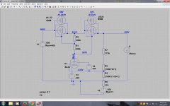
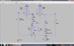
It is a (not so) conventional regulated supply with series pass tube(s), I´m using two 6336 (which I already have at hand) in series since I want 0-600V and their max Vp is 400V. The problem i´m having is the control tube, which has to be able to handle 595V on its plate with the output set at 600V to -160V with the output set at 0v. If I want to use a usual voltage reference at the cathode of the control tube, assuming 60V drop at min output, the tube should be able to handle 595-(-220V)=815V anode to cathode. The only tube that comes to mind able to handle near that is an EL34 (800Vp max), but obviously there must be a better solution. I thought about making the cathode voltage reference vary in accordance to the output voltage but somebody might propse something better.
I attached the LTspice simulations so you can see what I´m talking about, voltages on top of series pass tubes are anode to cathode and grid to cathode. If someone can come up with a solution it´d be much appreciated.
Attachments
If someone can come up with a solution it´d be much appreciated.
How about two floating 0-300V supplies, with their outputs in series? We've done this reliably for years.
They could be connected as master-slave. Here's a commercial example:
http://www.magna-power.com/support/kb/1008
Last edited:
How about two floating, lower voltage supplies, with their outputs in series?
That was my plan B. I want to be able to continously sweep from 0 to 600V, and with that configuration it would imply having a dual ganged pot for each supply with each pot having very different DC potentials which I am not sure it can withstand.
Edit: As I was replying you edited your response, what do you mean "master-slave" connected?
what do you mean "master-slave" connected?
In master-slave operation, one supply's voltage control adjusts both of the (in series) outputs simultaneously.
This can also be done for current, in parallel operation. Many inexpensive dual supplies can do both.
An example: http://www.tequipment.net/InstekGPS2303.html?Source=googleshopping&gclid=CJv-4NLYgsoCFQyFaQod7PQKMw
Last edited:
I simulated the circuit but I think it´s for fixed loads, I´m getting like 2.5K output resistance, otherwise it does prevent the control tube from seeing the large voltages.
Back to the original design, I looked thorugh some old commercial bench supplies and almost all exceed the max plate voltage for the control tube (and some even exceed max plate to cathode voltage for the series pass tubes). For example, my heathkit IP-17 puts like 550V plate to cathode on a 6AU6 when the output is set to 400V! And when the output is at 0V the 6L6´s have to drop the full rectified 600V. What I think, is that since their are no great AC signals present anywhere, one can stretch the max voltage ratings of the tubes, which are for AC amplifiers and thus account for positive peak voltages.
Back to the original design, I looked thorugh some old commercial bench supplies and almost all exceed the max plate voltage for the control tube (and some even exceed max plate to cathode voltage for the series pass tubes). For example, my heathkit IP-17 puts like 550V plate to cathode on a 6AU6 when the output is set to 400V! And when the output is at 0V the 6L6´s have to drop the full rectified 600V. What I think, is that since their are no great AC signals present anywhere, one can stretch the max voltage ratings of the tubes, which are for AC amplifiers and thus account for positive peak voltages.
FWIW, a ГУ-50 (GU-50) will take up to 1000V (A-K) with no problem (up to 45MHz anyway)....the tube should be able to handle 595-(-220V)=815V anode to cathode...
As cheap as chips and durable as rock.
Well, it was long ago, but I've solved problems like this very effectively with analog optoisolators and floating bias supplies. It's also possible to use little ferrite-core transformers or low-value (e.g. 100pF) HV caps to couple high-frequency AC control signals across the voltage boundary. Some folks have even used piezo-ceramic 'transformers' (transducers) for this job. How about a couple of ceramic tweeters welded face-to-face? 
I simulated the circuit but I think it´s for fixed loads, I´m getting like 2.5K output resistance, otherwise it does prevent the control tube from seeing the large voltages.
Back to the original design, I looked thorugh some old commercial bench supplies and almost all exceed the max plate voltage for the control tube (and some even exceed max plate to cathode voltage for the series pass tubes). For example, my heathkit IP-17 puts like 550V plate to cathode on a 6AU6 when the output is set to 400V! And when the output is at 0V the 6L6´s have to drop the full rectified 600V. What I think, is that since their are no great AC signals present anywhere, one can stretch the max voltage ratings of the tubes, which are for AC amplifiers and thus account for positive peak voltages.
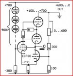
Well after all it was only an idea
 ,puting the controls on the low side to prevent high voltages.Perhaps there are other ways to do that
  .
.Back to the first one.I think a ECL82 can do.Is made for vertical deflection in TV, see there high voltages too.
And 600V for a 6L6 is to much but if you use a (electrical the same) 807 with top anode it's ok.
Mona
A GU-50 is an overkill for the control tube (as is the EL34). The ECL82 is more like it and I also have a couple of them so unless someone can point me to a better alternative it is probable I´ll end up using those.
The optocoupler idea is very neat indeed, I might look into it if I end up to paranoid about using the ECL82 at high voltages, thanks.
The optocoupler idea is very neat indeed, I might look into it if I end up to paranoid about using the ECL82 at high voltages, thanks.
What's the maximum current requirement?
I doubt I´ll go past 200ma which would only be of concern below 200V output according to what I sketched on the 6336 plate curves. I just want it to be as versatile as possible for who knows what experiments in the future.
I recall there were some bench supplies that used thyratrons that might fit the bill, the probelm might be sourcing the tubes... The advantage of the thyratron is that it can handle rectification and regulation at the same time.
Hmm, I also had in mind a low voltage high current PS with those. The problem is that they dont deal with the output ripple which must be filtered, and adding chokes adds expense and output resistance.
Although if I use them as a variable output rectifier feeding into a typical series pass regulator (one tube though), and vary both at the same time, I could get the series pass element to always drop low volts, which would mean it could always pass almost full current (at least until the thyratrons start dissipating to much). What do you think? It sounds pretty neat!
Are you determined to keep this all tube?
I only ask as there are a bunch of depletion mode MOSFETS that will handle 800V (or more) D-S.
When I built my lab HV supply, I used an LDO regulator between gate and source of a D.M. MOSFET. It goes down to 200V (or even lower, depending in dissipation) and up to >1kV. Runs very cool at 500V and up and has been working reliably for going on four years now.
Just a thought.
That's what I figured!Yeah, I´d like to keep it all tube despite knowing how much easier it would be with SS electronics, like a challenge lets say
Good luck. I'm sure you'll work it out.
I don't have any experience with thyratron PS, but it seems adding a series pass regulator only complicates the matter further. Decent LC filters would still be my preference... not very creative, I know.Although if I use them as a variable output rectifier feeding into a typical series pass regulator (one tube though), and vary both at the same time, I could get the series pass element to always drop low volts, which would mean it could always pass almost full current (at least until the thyratrons start dissipating to much). What do you think? It sounds pretty neat!

- Status
- This old topic is closed. If you want to reopen this topic, contact a moderator using the "Report Post" button.
- Home
- Amplifiers
- Power Supplies
- Help designing regulated power supply