What about the steve bench power supply?
Tube Based Voltage Regulators - Part 3
Or this wonderfull example of a supply built by Pmillet.
High-voltage bench supply
I built a version of this supply with two PL519 tubes, worked well.
A tektronix power transformer is ideal for this kind of supply, plenty of windings. 3 high current windings, and two windings that can be used for a dedicated screen/Bias supply. i dont know where you're located but there are a couple on ebay for cheap in the US
It is not needed to float the cathode of the error amplifier on -90V unless you plan to include a 0 volt capability into the supply. I'd personally recommend not floating the cathode as this gives better load regulation due to the lower cathode inpedance.
When stabilizing the reference voltage a 150V regulator tube feeding a 85 volt regulator tube, say a 85A2 gives an amazingly stable -85V for the reference part.
@AA i dont know what kind of iron you have laying around but i'd be happy to help out if you need, because the voltages are fixed you might be best served using either 6080 twin triodes or any of the other voltage regulator tubes.
There is also the option of using some transistors to increase the performance of a power supply consideraly.
see the attachment, this is a supply where the error amplifier sees a constant current source as plate load, and because pentodes have essentially flat curves, this means that a load change (and hence a shift in cathode to grid voltage does not require a shift in current from the error amplifier) and hence its grid voltage remains unchanged.
perhaps you could use the IXP10M45S to do this.
Just my 2cts
Attachments

I think the OP wants to go up to 600V, both of the above designs max out at 450V.What about the steve bench power supply?
Tube Based Voltage Regulators - Part 3
Or this wonderfull example of a supply built by Pmillet.
High-voltage bench supply
Going down to zero is important so i can do continous sweeps from 0 to 600. Regarding topology I´m almost settled on using thyratrons as grid controlled rectifiers to vary the unregulated DC and have a nearly constant voltage drop on the pass tubes. Right now I´m pretty busy, but I´ll try and draw a schematic of what the rectifier section would look like.
I just did a crude schematic of what a thyratron grid controlled fullwave bridge should look like. This way, I should be able to use the 1300V PIV thyratrons and still get a maximum rectified DC of around 800V (more than I originally wanted).
I have two questions. First is if the phasing of the grid transformers (T1, T2 and T3) is correct, in reality they would all be wound on the same core and share the same primary which would be fed from the phase control filter.
Second question is if the circuit would work at all 😀
I have two questions. First is if the phasing of the grid transformers (T1, T2 and T3) is correct, in reality they would all be wound on the same core and share the same primary which would be fed from the phase control filter.
Second question is if the circuit would work at all 😀
Attachments

Never seen one before... Are you going with the bridge or the FW version? And which tube are you going to use?Do you have thyratron models for LTspice? I tried searching but came up empty handed.


Never seen one before... Are you going with the bridge or the FW version? And which tube are you going to use?
Almost certainly the bridge. As for tube options I have the following (all have 1300 PIV):
2050: 3,8 watts to heat it, would give max current of 200ma
EN32=S1,3/2iV=6574: 6 watts to heat it, would give max current of 600ma
6012: 16,4 watts to heat, would give max current of 1Amp
EN32 is the best option, though I can´t source them locally (just ebay) so first I´ll try experimenting with 2050´s or 2d21´s which are far more common. I´ll post results when I get to do so (maybe not in the near future).
How about this? I would like to make simple tube supply in future.
I would be thankful if you try this out.
This is most important page fro sheet
I´m not so shure how that would work since the circuit is only varying the duty cycle of half the rectifier bridge (the thyratrons) to vary the output. I´m sorry but I have no transistors or opamps so I can´t test the circuit, will let you know about the all tube version though.
i wired dc supply to grids & cathodes.
been able to regulate 0-max. (-7..0) 🙂
this principle seems work.
no need for peaking trafo
been able to regulate 0-max. (-7..0) 🙂
this principle seems work.
no need for peaking trafo
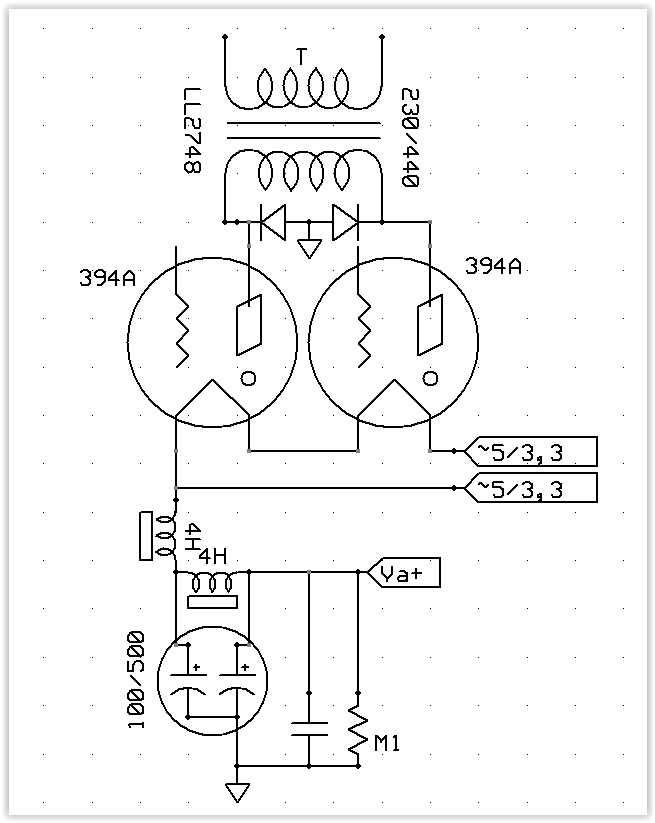
Hy a final schematic diagram of am PSU using thyratron (ex WE 394A in tap mode - 2 diodes, 2 thyratrons or 1 diode Si avalanche type + 1 thyratron... preffered) I have only one new (ya it should be 2... but I didn't find it in Romania yet ...) for an 370-430v CC -ish / 300mA min ?? THX!
- Home
- Amplifiers
- Power Supplies
- Help designing regulated power supply