Hi all
I need help with this...
I have 6 channel of those P1.7
and have hard time understanding how to make them work...
those are Koja PCB
have solder all the parts, except those relays as I have no plan to use tham
the input is SE so I shorted pin 1 and 4 on first relay...
Now I power it, with around 60V (more like 65V AC) and have 60V regulated
Q23 (on original P1.7) scheme is relay hot...can't touch it...but it have 60V on output..
the thing is that I don't get nothing on output
I have connect input and try with small speaker at the + and 0, or - and 0... but no sound
does any one have idea, did I skip to solder something, some jumper as I don't use those relays ?
here is the picture
HAHHAAahahhahCan't help you with P1.7...but you got a nice Alfa Romeo")
Tnx...
I think that pcb should work without relays...but...
Will have to check did I solder everithing at right place
If highly reccomend the relays! In my case I have balanced and unbalanced sources and amplifiers. The relays and a couple switches makes that so easy to deal with and the P1.7 is an excellent active source converter. I was also anti-relay at first, but man are they handy.
I also used the Panasonic caps that were used in the factory built Aleph P's rather than the Wimas. The Panasonics are smaller and a lot less expensive. I believe they were less than $8.00 USD each from Mouser. The line stage sounds superb!
Mark Allen
I also used the Panasonic caps that were used in the factory built Aleph P's rather than the Wimas. The Panasonics are smaller and a lot less expensive. I believe they were less than $8.00 USD each from Mouser. The line stage sounds superb!
Mark Allen
[/ATTACH]
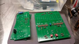
I'm not sure where you have jumpered. You only need to put 2 jumpers on RLy 2 which is right beside the input connections. The jumpers go between the end pads on each side of the relay. See the attached photo of one of my boards.You can see the jumpers which have white heat shrink on them, just to the right of the input cap. I am using Axon caps. 30uf for outputs and 13uf for inputs.

Hi all
I need help with this...
I have 6 channel of those P1.7
and have hard time understanding how to make them work...
those are Koja PCB
have solder all the parts, except those relays as I have no plan to use tham
the input is SE so I shorted pin 1 and 4 on first relay...
Now I power it, with around 60V (more like 65V AC) and have 60V regulated
Q23 (on original P1.7) scheme is relay hot...can't touch it...but it have 60V on output..
the thing is that I don't get nothing on output
I have connect input and try with small speaker at the + and 0, or - and 0... but no sound
does any one have idea, did I skip to solder something, some jumper as I don't use those relays ?
here is the picture
I'm not sure where you have jumpered. You only need to put 2 jumpers on RLy 2 which is right beside the input connections. The jumpers go between the end pads on each side of the relay. See the attached photo of one of my boards.You can see the jumpers which have white heat shrink on them, just to the right of the input cap. I am using Axon caps. 30uf for outputs and 13uf for inputs.
Last edited:
Oscillations on Aleph J board
Hi folks
Just a heads up. I powered up my boards and did some basic DC checks. The basics looked Ok. I shorted one input to ground and hooked up my signal generator. It seemed to be working but I had a large imbalance (10%) in the +and_ outputs. The 20ma current sources also seemed to be imbalanced.
I had to leave it until I got home tonight. I had a suspicion that the circuit could be oscillating. Sure enough, I got out the scope and found the output had RF riding on the 1khz sine wave. The oscillation frequency was about 8mhz. It was more on one phase then the other, depending on which input was grounded. I found that the 20ma current sources Q12 and Q14 were oscillating. The Fets and transistors both have stopper resistors of 221 ohms. I took a second 221 ohm resistor and placed it in parallel with these resistors. Lowering the value of the gate stopper caused the oscillation to stop while lowering the base stopper resistor caused the oscillations to increase. It seemed counter intuitive to lower the gate stopper so I replaced the base resistors R52 and R67 with 499ohms and the problem was fixed. I now have a balance within .01volts with an output of 10volts on each phase.
If anyone experiences a similar imbalance it should be a symptom of an oscillation. A scope is very handy to have for situations like this!
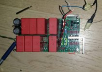
Anyone recognize these Aleph 1.7 PCBs?
I've been planning on ordering the remainder of the parts but wanted to do a little research on their origin before I buy anything. They look pretty true to the schematic but I wanted to check just in case...
Thanks
I've been planning on ordering the remainder of the parts but wanted to do a little research on their origin before I buy anything. They look pretty true to the schematic but I wanted to check just in case...
Thanks
Attachments
If highly reccomend the relays! In my case I have balanced and unbalanced sources and amplifiers. The relays and a couple switches makes that so easy to deal with and the P1.7 is an excellent active source converter. I was also anti-relay at first, but man are they handy.
Mark Allen
I will use only SE inputs, and it will be a part of DSP so I don't need to swich anything, once it start to play music
[/ATTACH]
I'm not sure where you have jumpered. You only need to put 2 jumpers on RLy 2 which is right beside the input connections. The jumpers go between the end pads on each side of the relay. See the attached photo of one of my boards.You can see the jumpers which have white heat shrink on them, just to the right of the input cap.
Thanks Bfpca
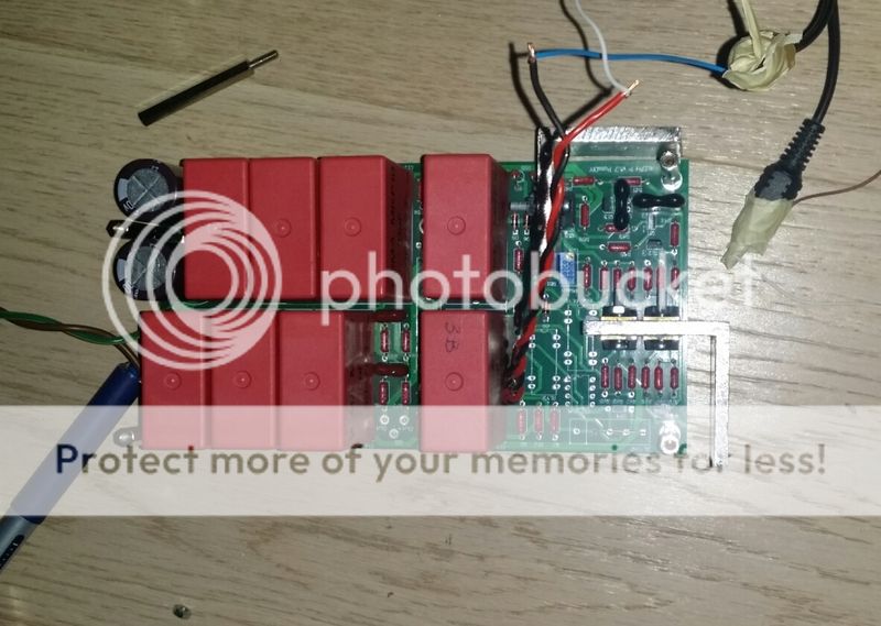
On picture, belowe, I have draw with ''red'' what I have jump over ( as I understand, it should be jumped for SE inputs )
and will place ''yellow'' jumpers as you advised, once I get home from work
I hope it will do the trick but I'm affraid I did something wrong as I tought that it should play withot those jumpers that you have placed
will see...thanks
Attachments
Last edited:
Anyone recognize these Aleph 1.7 PCBs?
I've been planning on ordering the remainder of the parts but wanted to do a little research on their origin before I buy anything. They look pretty true to the schematic but I wanted to check just in case...
Thanks
Looks like the "Veteran Boards"
See also this thread.
Regards,
Nick
I will use only SE inputs, and it will be a part of DSP so I don't need to swich anything, once it start to play music
Thanks Bfpca
On picture, belowe, I have draw with ''red'' what I have jump over ( as I understand, it should be jumped for SE inputs )
and will place ''yellow'' jumpers as you advised, once I get home from work
I hope it will do the trick but I'm affraid I did something wrong as I tought that it should play withot those jumpers that you have placed
will see...thanks
Yes, the red jumpers would ground the - input and allow SE operation. The jumpers I put in are to bypass the 10k attenuator resistors R5 and R6. I did not put them in on my build. If you have the attenuator resistors installed you would still get an attenuated signal through them without the jumpers I used. I don't think that is your problem. It looks like you have separated the power supply from the rest of the board. If Q23 is getting hot then you can measure the voltage drop across the 3.3 ohm resistor R73 to determine how much current the board is drawing. It should be somewhere around .23 volts for a typical 70ma current draw. This will give you some idea if the current sources etc. are working.
You can also measure the voltage drop across the 22.1 (R44,59) and 33 ohm (R55,70) resistors that set the currents. They should be in the .65v range.
no luck, still no sound when I connect speaker on unbalanced output + and 0 (- stays unconnected)
I should have sound when I play something and connected this way ? (with SE input + and 0 (shorted to -)
I have
0.22V over 3.3 for around 59.6v
have 0.61V on R44 and R59
and 0.63V on R55 and R70
whats next to check
tnx
(is there some place (schematic) where I can check referent voltages (over resistors etc.) for P1.7 ?)
Last edited:
Those readings all look good. Using a speaker to measure the output is not the best plan. The output impedance of the Aleph p without the attenuator is about 2kohms so you won't get much sound from a low impedance speaker across the output. you should be able to use a DVM on AC volts to measure the output. If you do not have the gain control shorted or wired up with less than 2k resistance you will get very low gain. If you short it you should have a gain of something like 8. If you are using music as a source you should still see a fluctuating AC output voltage on the meter display.
I am still trying to figure out what is causing the distortion on my RelVol3 boards from Dantimax.
Using a DMM I checked the attenuation of each of the 63 steps and found that it increases with each step, as expected. This rules out mistakes with resistor placement and shows that all relays work.
Previously I used an analog scope to visualise the distortion that occurs during volume changes. See http://www.diyaudio.com/forums/pass...1-7-preamp-builders-thread-8.html#post4519705
At that time I ran the test on one of the lines only. I have now re-run this test on all attenuator lines (L+, L-, R+ and R-) and found similar distortion on all lines.
Just in case switching the relays was too much for the local on-board 47uF cap to handle (what do I know? Perhaps it was defective), I replaced it by a new 100uF. Same problem.
I re-ran the test powering the Dantimax boards using a commercial 5V 3A SMPS. Same problem.
Still no reply to my emails from Mikkel (Dantimax). Any help is appreciated.
Thanks,
Albert
I was thinking that P1.7 have enough ''power'' to drive speaker...
will try to measeure some AC at the output...
maybe play 1khz sound to see what will I get...
tnx
I have some reading when play 1kHz tone (from tone generator), so Ibelive it's working
will take some time before I connect it to some amplifier...
still have some work to do
\ 5 more to go thanks all for help
Bfpca I own you a beer, let me know when you come to Croatia
I'm working on my schematic, and have some questions:
Input Dipswitch
Dipswitch 1-4, manual says you can damp in signal with 12db, with 1,2 ON and 3,4 off and vice versa. What damping will you get if you have all ON or OFF ?
Just curious if you can have 0db, 6db, 12db or 24db damping ??
- - -
Balanced vs Unbalanced Input/Output
I never used balanced cables, and have some questions.
* Normally you just terminate the unused XLR contacts when using RCA.
Can you use RCA on Input and XLR on Output ? (In manual it says it work)
* If you have RCA in and out, do you need to terminate output ?
- - -
KOJA PCB Questions:
On Kojas fine pcb you have 2x relays for Input and Output... Why ?
If you use RCA, and terminate the XLR contact it should be enough. Also if you prefer to use the relay to do it, you need to remember that you the use it if you change back to XLR. I can only find it useful if you only have 1x input and instead of terminate the XLR contact, use the dipswitch to active relay.
Also, what's the use for the Output relay since the manual says you can use either without terminate it.
Please enlighten me...
I have some reading when play 1kHz tone (from tone generator), so Ibelive it's working
will take some time before I connect it to some amplifier...
still have some work to do
thanks all for help
Bfpca I own you a beer, let me know when you come to Croatia
No problem Yoke, you can email me the beer!
Glad to hear you are making progress.
I'm working on my schematic, and have some questions:
Input Dipswitch
Dipswitch 1-4, manual says you can damp in signal with 12db, with 1,2 ON and 3,4 off and vice versa. What damping will you get if you have all ON or OFF ?
Just curious if you can have 0db, 6db, 12db or 24db damping ??
- - -
Balanced vs Unbalanced Input/Output
I never used balanced cables, and have some questions.
* Normally you just terminate the unused XLR contacts when using RCA.
Can you use RCA on Input and XLR on Output ? (In manual it says it work)
* If you have RCA in and out, do you need to terminate output ?
- - -
KOJA PCB Questions:
On Kojas fine pcb you have 2x relays for Input and Output... Why ?
If you use RCA, and terminate the XLR contact it should be enough. Also if you prefer to use the relay to do it, you need to remember that you the use it if you change back to XLR. I can only find it useful if you only have 1x input and instead of terminate the XLR contact, use the dipswitch to active relay.
Also, what's the use for the Output relay since the manual says you can use either without terminate it.
Please enlighten me...
1.) About the Attenuator switches, one set of contacts is for the series resistor of 10K, the other is for a shunt to ground of 3.32K. If you set the switches to bypass the 10k and leave the 3.32k to ground you will lower the input impedance to 3K or less and you won't get any attenuation, unless your source has a relatively high output impedance.
If you leave the 10k in the circuit and do not have the 3.32K connected to ground you should get about 6db attenuation if the input impedance of the Aleph P is 10k.Note that you can change the values of the resistors if you want to have a different level of attenuation.
2.) You do not need to short the output to ground when using balanced inputs. You can simply short the - input on the XLR to ground and use a SE input. If you don't have a copy of the owners manual for the Aleph P1.7 you should download it and read it. It is quite informative on operation of the preamp and also on the design philosophy.
I'll let Koja comment on the PCB questions. Good luck with your build.
I am still trying to figure out what is causing the distortion on my RelVol3 boards from Dantimax.
Using a DMM I checked the attenuation of each of the 63 steps and found that it increases with each step, as expected. This rules out mistakes with resistor placement and shows that all relays work.
Previously I used an analog scope to visualise the distortion that occurs during volume changes. See http://www.diyaudio.com/forums/pass...1-7-preamp-builders-thread-8.html#post4519705
At that time I ran the test on one of the lines only. I have now re-run this test on all attenuator lines (L+, L-, R+ and R-) and found similar distortion on all lines.
Just in case switching the relays was too much for the local on-board 47uF cap to handle (what do I know? Perhaps it was defective), I replaced it by a new 100uF. Same problem.
I re-ran the test powering the Dantimax boards using a commercial 5V 3A SMPS. Same problem.
Still no reply to my emails from Mikkel (Dantimax). Any help is appreciated.
Thanks,
Albert
Albert, I just got a chance to watch and listen to your scope video of the noise. Is the nose we are hearing on the video coming from speakers? Or is it coming form the relays mechanical switching noise?
You will get steps in the change in attenuation with this setup versus a pot. One other thing occurs to me. I am not familiar with the attenuator you are using, but is it possible that it leaves the amp inputs open circuit during the switching period of the relays. If that is the case you could easily correct it by adding a high value resistor (100k maybe) across the attenuator output.
1.) About the Attenuator switches, one set of contacts is for the series resistor of 10K, the other is for a shunt to ground of 3.32K. If you set the switches to bypass the 10k and leave the 3.32k to ground you will lower the input impedance to 3K or less and you won't get any attenuation, unless your source has a relatively high output impedance.
If you leave the 10k in the circuit and do not have the 3.32K connected to ground you should get about 6db attenuation if the input impedance of the Aleph P is 10k.Note that you can change the values of the resistors if you want to have a different level of attenuation.
From the service manual:
The input pad settings are as follows (only 3 settings)
1.3 dB 3,4 5,6 on
9.7 dB all off
15 dB 1,2 7,8 on
Ok, then if I'm correct on Koja's PCB you can only have 2 settings instead of 3. Not a big problem. I just wanted to be sure.
Strange, in manual it says:
The switch default position is 1,2,7,8 = ON and 3,4,5,6 = OFF. For a 12 dB input attenuation, 1,2,7,8 = OFF and 3,4,5,6 = ON.
This switch can also be used to effectively lower the gain of the preamp by 12 dB. It does not otherwise affect the performance of the preamp.
- Home
- Amplifiers
- Pass Labs
- Pass Aleph P 1.7 preamp builders thread