Feedback for mid frequency driver/amplifier.
the decoupling has to remain to satisfy all the medium frequency and high frequency transient demands for current.
Keep the same high values as for the bass amp.
I suggested 100nF to 220nF and 470uF to 1mF, if those are allowed.
If you want/require capacitance tolerance for the output then add an L||R.
all the previous comments apply.
Last edited:
Pin 4 is clean for sure--That is the ground for the mute circuit, located at input of the voltage amp. It is one device away from the + input, and serves as an additional (albeit slightly poorer) input.I don't know which of the chipamp ground pins is clean, or dirty. I don't like the haphazard linking of all the signals to these unknown gnd pins.
Poorly documented feature: Pin 4 can be padded with a series resistor for use as input divider along with driving the mute switch from the clip detect (no idea if direct or needed a transistor), forming a compressor limiter, but nobody uses that feature (due to cheap symmetrical clip detector that has very poor resolution with asymmetrical signals, such as music). As that feature just isn't used, I've removed the bulky extraneous parts from Pin 10.
Pin 1 isn't really dirty--That is ground for the standby circuit, located near output of the voltage amp. The signal there is potentially big, but the current isn't.
Last edited:
For output zobel, let's say that I used a 4.7 ohm resistor, and then what would be a reasonable cap value range?I would cheat and use a simulation of the complete amp and PSU. I am not into the filter approach but see the capacitors as current supplies when used in a PSU.
If I'd have used 470n, that's down by 3 at 72000cps, down by zilch at half that, and probably won't clip the audio band, right?
But, that cap sure does look too big, on just appearance, at least.
Last edited:
Wow, what an overwhelming flurry of responses! (must be true what they say that a picture is worth). This will certainly take me some time to digest. Thank you all for the feedback, and glad to see Mark's joined the discussion. I hope to post some revised schematics and BOM's soon.
Sixto.
Sixto.
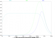
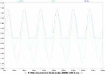
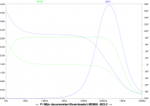
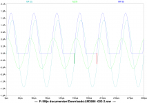
Oh, that does look better. However, would you prefer 100n or 47n?Zobel current I(C4) with 470nF, 4.7R compared to I(C7) with 100nF, 4.7R.
I(R11)= load current.
The real TDA7293 amp is slower basic miller type pushing cheap fets, and not prone to amplify RF.
Last edited:
100n or 47n, I don't think you need to decide now. If you are still in the layout stage you can design for either. The current is more important for determining physical size of the resistor.
AndrewT questioned the connection of the GND pins to audio GND. For me if they are not a part of the audio input then I would connect to power GND.
AndrewT questioned the connection of the GND pins to audio GND. For me if they are not a part of the audio input then I would connect to power GND.
I think your sim modeling is correct.
The 470nF is far bigger than any I have seen in any sch. The normal range is 47nF to 220nF, with the vast majority using 100nF.
Bigger nF does mean more dissipation in both the resistor and in the esr of the capacitor.
Use a low esr high voltage capacitor.
The capacitor voltage rating does have to be de-rated for high frequency duty. The few I have looked up need a lot of de-rating.
I use 250V MKT in either 47nF, 100nF, or 150nF for the Zobels.
I tend to use multiples. it is some years since I last used a single Zobel in a Power Amplifier. The last is in the Pi output filter with the R+C across the speaker terminals.
This "spread" Zobel philosophy recently suggested by R.Cordell allows lower value capacitors to be used, but with the same total capacitance.
Thanks! And, then we have these (attached).
We're not likely to see any "in the wild" because this is DIY and they're likely to get modded (no matter how nice they are if not modded). Therefore, the normal usage for these is the solid place to start that was not provided by the datasheet.
The under-volted 45W example will image better (used along with 20-0-20 and 22+22 transformers). At the expected voltage (printed on the schematic) and with the assumption of excellent compact (I mean tiny!) layout and route the gain divider's resistors most directly (rather than most decoratively), then the cermet trimmer is set to 780R but can be fiddled to support different applications, including different voltages and other modding. Of the two schematics presented below, the lower voltage example has higher resolution. Sounds like a hi-fi.
However, the #1 most popular mod for amplifiers is a push for power build. So, I generated a second schematic showing the higher rails and different gain setting involved (used along with 25-0-25 and 28+28 transformers). Note the cheap little 680R film resistor has not performed optimally as a base stopper; however, if you replace that with a cermet trimmer, you can dial it to 730R. Also, the series elements are high efficiency MBR1645 schottkies, which have smallest voltage drop but still work just barely well enough to secure the excellent power decoupling necessary for clear audio.
Some of the imaging/3d/realism quality of the undervolted 45W example isn't accomplished by the higher power 65W example, and that's the cost of 20 more watts, which won't boost the speaker output by so much as 1.5db--certainly not worth the compromise, except for people who equate watts with quality. That is actually popular. The higher power version (with higher voltage rails), has a pretty tone and will certainly work well enough to rock the house for a party and for woofer amplifiers as well. Sounds like a party amp.
Attachments
Last edited:
Working towards a more complete understanding...
Hello team, thanks again for all your feedback. Let me try to dig a little deeper into some comments to get a better understanding:
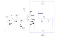
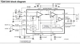
1) Agreed, I had wondered about this when I examined 3 different TDA7293 boards I purchased to test and sample. All of them had the Input and Ouput Return Signals plus Power Ground traces flowing into each other. Even the datasheet schematic is unclear about this (see attached below). No excuses for bad design, I'll keep separate Power Ground from Input Signal Return on the next sketch. (what about Output Signal return?)
2) Sounds good to me. I can build the boards without input filters and always add filters later if I find that noise is creeping in.
3) If input filters are needed, I can/will reduce R1 (is a factor of 10 enough?)...1K/47uF gives the same HiPassFilter value.
4) The datasheet recommends 100nF.
5) The datasheet calls for a single 1000uF in parallel with the 100nF. This link below plus earlier posts on this here thread have made convincing arguments for using multiple parallel capacitors: http://www.diyaudio.com/forums/power-supplies/214869-single-vs-parallel-capacitor.html Could it be that this specific condition is pushing beyond the point of diminishing returns?
Ok, this will keep me rolling as I comb through the other responses.
Hello team, thanks again for all your feedback. Let me try to dig a little deeper into some comments to get a better understanding:
Feedback for low frequency driver/amplifier... I don't like the haphazard linking of all the signals to these unknown gnd pins...
1) Agreed, I had wondered about this when I examined 3 different TDA7293 boards I purchased to test and sample. All of them had the Input and Ouput Return Signals plus Power Ground traces flowing into each other. Even the datasheet schematic is unclear about this (see attached below). No excuses for bad design, I'll keep separate Power Ground from Input Signal Return on the next sketch. (what about Output Signal return?)
...If the crossover is screened and the power amp is screened then external interference can't get in.
If all your signal connecting pairs are twisted then these limit internal interference . On that basis you may not need any input filters between the cross over and the power amp...
2) Sounds good to me. I can build the boards without input filters and always add filters later if I find that noise is creeping in.
R1b is high, too much noise?
3) If input filters are needed, I can/will reduce R1 (is a factor of 10 enough?)...1K/47uF gives the same HiPassFilter value.
C6a & 8a seem very small. Is that a datasheet recommended value?
4) The datasheet recommends 100nF.
C6b,c &8b,c don't need to be split.
5) The datasheet calls for a single 1000uF in parallel with the 100nF. This link below plus earlier posts on this here thread have made convincing arguments for using multiple parallel capacitors: http://www.diyaudio.com/forums/power-supplies/214869-single-vs-parallel-capacitor.html Could it be that this specific condition is pushing beyond the point of diminishing returns?
Ok, this will keep me rolling as I comb through the other responses.
Attachments
Since we're not using the amp in quad rail form, then in this simpler form, some of the energy to power the speaker will come out of the decouplers. When this is done, it works for harmonic support and should not be sized large enough to power midbass fundamentals--we don't want the shields dropped very far down and we don't want an overlong timer delay to outwait before proper function returns.5) The datasheet calls for a single 1000uF in parallel with the 100nF.
The electrolytics:
My 440u (with at least MBR1645) will support baritone harmonics for more easily hear-able bass. It is unlikely that a larger size is required; however, 270u||270u is doable and Panasonic does make those.
See also the Honey Badger schematic's power circuit for more information. That's a quad rail, but it has the right size electrolytic caps. You don't need to imagine what would happen if I had to compress that down to split rail, because the result is on my TDA7293 schematic already. See also Hafler.
With TDA7296(4) and TDA7293, the position for the electrolytic caps is tight up against pins 7 and 8, voltage amp power.
The bypass caps:
Those pasted everywhere 100n that infest most schematics, need to be a Ceramic cap, disc or X7R, except for cases when you've used the right size cap, which is unlikely to be 100n in All cases.
The Ceramic disc and X7R tolerate careless wrong-size foobar bypass, such as shown in the TDA7293 datasheet. Use those specific ceramic materials and you can usually get away with the wrong size bypass caps.
Anyway, the position for the bypass caps, and the power cable, is tightly close to pins 13 and 15, the output devices.
Quad rail:
Connect a high efficiency shottky clipper, such as inversely parallel pair of MBR745, between pins 8 and 15 to prevent explode. The diodes must be considerably more efficient than the parasitic capacitance inside the chip, else it will crack the substrate and burst into flames. It is only after you've bypassed that problem that you can play with quad rail power.
Next, then you can see that the 220u caps go on pins 7 and 8 and then the 1000u caps go on pins 13 and 15.
That's where the 1000u caps go, and if you don't have quad rail power, then likewise you don't need any 1000u caps for this amp.
See also Ilimzn's materials at post#58 and elsewhere, including here:
![320317d1356838465-optimizing-tda7294-output-tda7294_ilimzn.png]Quad Rail](https://www.diyaudio.com/forums/attachments/chip-amps/320317d1356838465-optimizing-tda7294-output-tda7294_ilimzn.png]Quad Rail)
For when you've got different rail voltages, Ilimzn has shown the schottky+zener protector for the chip substrate.
So, two of ordinary 20% caps, or four of better 10% caps, or eight of specialist 5% caps, or approximately twenty-five of rare 1% caps. Indeed, diminishing returns are possible.This link below plus earlier posts on this here thread have made convincing arguments for using multiple parallel capacitors....Could it be that this specific condition is pushing beyond the point of diminishing returns?
Like a zombie attack principle: I don't have to run faster than everyone--I only have to run faster than you.
Likewise, big cap arrays are trying to have tighter dampening than the whole planet. My version with the tandem caps and series element (minimum loss is with MBR1645), more certainly defines what portion of the power circuit is the local decoupling and what is not.
Last edited:
I like to think of my zombies as being better organised. When the 1uF zombies are killed they are replaced by the 100uF zombies and they are in turn replaced by the 10000uF zombies. They get promotion and therefore are able to move faster.
I forgot you can't kill zombies, they are already dead.
I forgot you can't kill zombies, they are already dead.
Last edited:
Trying hard to stay grounded and ahead of zombies.
Laughing out loud at the office. - thanks for that too!
Hi Daniel, I'm not ready to go to quad-rails quite yet. I'm all for simplicity as shown in your Higher-fidelity, lower voltage / Lower gain configuration. Dual 220's or 270s are fine with me. I'm even less likely to run out of gas with narrow-band amps, right?
I'm currently researching grounding schemes for amp boards. There is a lot of information, much of it is confusing. I get the basic idea that signal and power should be separate. But, don't they all lead to the same place eventually? How do we keep one ground from picking up noise from other grounds? (hope I can find some nuggets in Bob Cordell's book arriving tomorrow)
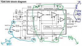
I've attached an interpretation of the datasheet schematic grounding scheme...Lt-Blue on the left side is Small-signal return AC, the 4 center Green nodes should all return to the high-current 0-voltage DC power ground, Dark Blue on the right is amplified AC signal return. The grounding is similar to other TDA7293 schematics I've seen. Any suggestions from the membership to minimize signal contamination?
Thanks - Sixto.
Laughing out loud at the office. - thanks for that too!
Hi Daniel, I'm not ready to go to quad-rails quite yet. I'm all for simplicity as shown in your Higher-fidelity, lower voltage / Lower gain configuration. Dual 220's or 270s are fine with me. I'm even less likely to run out of gas with narrow-band amps, right?
I'm currently researching grounding schemes for amp boards. There is a lot of information, much of it is confusing. I get the basic idea that signal and power should be separate. But, don't they all lead to the same place eventually? How do we keep one ground from picking up noise from other grounds? (hope I can find some nuggets in Bob Cordell's book arriving tomorrow)
I've attached an interpretation of the datasheet schematic grounding scheme...Lt-Blue on the left side is Small-signal return AC, the 4 center Green nodes should all return to the high-current 0-voltage DC power ground, Dark Blue on the right is amplified AC signal return. The grounding is similar to other TDA7293 schematics I've seen. Any suggestions from the membership to minimize signal contamination?
Thanks - Sixto.
Attachments
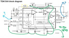
Hi Mark,
I've revised the datasheet grounding (attached) per your recommendation. Still have questions about what to do for grounding the Small Signal Return and Amplified Signal Return.
I highlighted R3 to address your second comment, I may have inadvertently erased part of the datasheet on the previous attachment, but there was no intent on my part to change the location of that resistor (still between pins 2 and 14) I am planning to use Daniel's 33K recommendation, though.
Thanks! - Sixto
Attachments
- Status
- This old topic is closed. If you want to reopen this topic, contact a moderator using the "Report Post" button.
- Home
- Amplifiers
- Chip Amps
- Optimizing TDA7294 Output