Just to update on this episode. Could not solve the audio muting problem. Looks like it's an interaction between my TV and Oppo 105. Problem can only be solved when the HDMI cable from the Oppo to the TV is unplugged. I also checked with Oppo 95 and faced the same problem.
Audio muting is in your case a consequence of repeatedly hand shakes which occur when you connect the device to your TV/display. Normally this hand shaking it happen at the connection moment. If this is repeated so many times to disturb the normal functioning of your player, it mean there is something wrong with the HDMI signal itself. Something there is not at it should, and your TV try to find out what is there on the HDMI connector.
I suspect the TV connector on its HDMI input. You may try to connect the player to another TV/display and observe if these sequenced hand shakes occur in the same way.
It may also be the HDMI output on your player.
To determine which of these devices it may have an issue on HDMI input/output a cross connecting of these devices should be tried.
Then the issue is quite clear (as I can see so far). The software in your Android TV it have a bug or a issue when about to recognize the HDMI signal coming from a larger spectre of connected devices. Your player is OK. The problem is the TV and its firmware. For sure Sony have to know about this, and they should fix it with an firmware update...
as I'm about to jump in the oppo mods (my 105D is working well, but I've seen how to improve it") ), I prefer to ask dumb questions first.
), I prefer to ask dumb questions first.
I'll do the PSU mod first, that's 110% sure.
I'd like also to maybe change the EIC plug, so I can upgrade the whole PSU chains... that make sense, or it's a fool's errand?
), I prefer to ask dumb questions first.I'll do the PSU mod first, that's 110% sure.
I'd like also to maybe change the EIC plug, so I can upgrade the whole PSU chains... that make sense, or it's a fool's errand?
In my opinion the EIC connectors, and main AC power cable are far from a serious and efficient mod. It for sure only benefit of this the sellers of these parts...
There are quite many legends about improved sounds after changing of these absolutely insignificant parts for the entire device functionality. Well, the legends are/still be only what it is: legends.
Of course these common components of any electrical device it have to have a certain quality to do the connection as it should, but more than this is just nothing to improve here, so to have impact over the outputted sound/picture of the device.
One can chose a better quality for these components, for a higher price. This is all right for perfectionists who may be able to invest more for their device. However, when about improvements for the final signals, in my opinion is pure and simple nothing. It can not be otherwise of course, as these parts are so peripheral in the whole device`s system, and so far from any influence over the sophisticated processing of the useful signals, at their impact in this area is a real zero.
As comparison I may mention the siltation when upgrading a car`s wheels decorations with some more fancy. There is obvious that such upgrading (not very cheap at all) it have nothing to do with the cars overall performances...
If you really want to do a improvement in this area of the device, I may suggest to use or made your shielded main AC power cable. Such it can improve the EMI noise level for the whole device. But do not expect a dramatic device`s overall quality changes.
You can also get a quite dramatic quality improvement for the outputted signals by doing another very simple upgrade/mod: replacing the original SMPS with a serial/analogue power supply. This it give by itself a significant quality improvement for both picture and sound.
Last edited:
103 player with forced ventilation...
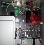
I recently modified an 103 model, and more than replacing the SMPS with a LPM and the standard clocks by my battery powered clock board, I thought to use a forced ventilation for the main processor. In this way the main processor (usually running at 45-50 deg.C) it run always at room temperature. The fan (through its mechanical mounting, as its low speed), is totally inaudible. The fan itself is however a low noise one...
The 103 models are very suitable for a forced ventilation, as these models it have enough space over the main processor. It is true that the 103 models do not have perforations in the enclosure, but creating a airflow inside the closed chassis, the heat transfer with the exterior it become however much more efficient.
My LPM designed for 105 models it already include an adjustable regulator stage special designated for a cooling fan. Now this stage it can be used for forced ventilation in 103 model too.
As I pointed before in many circumstances, lowering the processor working temperature it improve a lot its capabilities for a very high quality video signal. The results are really astonishing for picture. Both contrast, luminosity, tones gradients and colours are improved so. A general and very noticeable improvement.
The 103 models it can benefit much more of this improvements, as the available space inside the chassis it allow this mod much more easy. Lowering dramatically the processor working temperature in 105/105D models it can bring the same improvements for video signals, but this task it is a little bit more difficult to be realized, because a quite compact and full enclosure for these models.
Attachments
Last edited:
Even more, the 3,3v regulator for DVCC is an adjustable device. The designers maybe thought to lower the production costs, and did not provided this adjustable regulator with the right resistor divider to establish on its output 3,3v (it deliver actually 3,2v), and the necessary capacitor on its adjustable pin, to improve its noise parameters. This cap on the adjustable regulator device`s pin is a basic design rule to improve the regulator`s noise figures...
I don't get why they didn't use fixed regulatorfor DVCC as for VDD?
Well, the whole clue here is to be used the adjustable version of a such regulator, and not the fixed voltage one. And this for all these three chip power rails. However, there are not so many adjustable versions for the 1,2v regulators...
The adjustable version it can be improved for noise figures (lowering it), by adding that filtering cap on the adjustable pin. Unfortunately not the case in the original design....
In my mod I replaced the all standard quality regulators, by ultra low noise ones, special designed for this purpose, as adding a pre regulator for the analogue 5v rail. Another quality...
Double suspension elastic mounting for BD drive
I think to come back tot this modification, and show you here an improved version of my previous (quite old now) similar mod.
As known, Oppo use for the BD drive in all its player models, a completely wrong mechanical mounting approach. There are used some powerful springs under the BD drive, which are fully tensioned and in fact the whole mounting of the drive become a very rigid construction. Such mechanical design it not prevent any vibration to reach the sensitive BD drive device. The mechanical vibrations in the surrounded environment are induced into the player`s chassis, and are mainly coming from the amplified audio (bass sounds) into the room, while listening, the vibrations coming from the toroid transformer which is also rigid mounted on chassis. Any kind of lower or high frequency mechanical vibrations it goes directly into the drive optical system in the actual Oppo mechanical design.
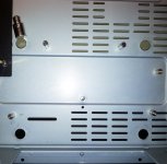
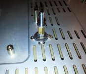
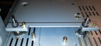
After a closer examination of this mechanical system for BD drive, I found out a way to improve it. This here is only one of the few other ways to improve the mechanical system. Some other solutions it can also be used, if the right components are available. With the components I could get, I made it so as you can see in the pictures here.
Some words about removing the original spacers from the chassis. These bolts are not so especially well fixed into the chassis. Are only pressed in, and are quite easy removable. To remove it, you may use a strong enough pliers. Strongly gripping the bolts with the pliers, try to move it in very small mouvements, increasing in small steps the movement`s amplitude, and do it in only the same one direction, back and forth. After you feel the bolt it move independently from the chassis, change the movement directions to a perpendicular one related to the previous. Then use the same small movements and increasing amplitude, until the bolt it get more disclosed. Repeating these movements, you will observe that the thin pressed parts of the bolts under the chassis, will broke. Repeat the operations until the bolt get completely disclosed from its hole. Do not try to rotate the bolt into its hole! Done!
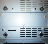
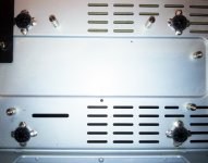
There is very important while disclosing these bolts to not distort the chassis flat shape. The disclosing operations have to be done very carefully, watching permanently and prevent as possible any deformation of the chassis bottom, as the shape of the holes itself. If any deformation from the flat shape may occur around the holes, then it have to be corrected using a small hammer and a contra heavy piece of metal on the other side. The eventual deformation of the round shape of the holes, have to be corrected too, by using the appropriate tools. If an increasing of the holes diameter may occur for one (while disclosing operations), then all the holes have to be corrected so to have identical diameters, and round shapes. This is important to further centre the rest of the components on the same original axes , and have the new bolts in exactly the same centred position as the original ones.
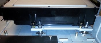
The flatness of the bottom part of the chassis is very important for the further operations when implementing the suspension/damping system. Some fine adjustments may be necessary at the end of the operation, to get the BD drive in exactly the same position as in initial design.
The rest of the mounting operations of this mod, are revealed by the pictures itself (pictures order).
If any questions, please ask.
I think to come back tot this modification, and show you here an improved version of my previous (quite old now) similar mod.
As known, Oppo use for the BD drive in all its player models, a completely wrong mechanical mounting approach. There are used some powerful springs under the BD drive, which are fully tensioned and in fact the whole mounting of the drive become a very rigid construction. Such mechanical design it not prevent any vibration to reach the sensitive BD drive device. The mechanical vibrations in the surrounded environment are induced into the player`s chassis, and are mainly coming from the amplified audio (bass sounds) into the room, while listening, the vibrations coming from the toroid transformer which is also rigid mounted on chassis. Any kind of lower or high frequency mechanical vibrations it goes directly into the drive optical system in the actual Oppo mechanical design.
After a closer examination of this mechanical system for BD drive, I found out a way to improve it. This here is only one of the few other ways to improve the mechanical system. Some other solutions it can also be used, if the right components are available. With the components I could get, I made it so as you can see in the pictures here.
Some words about removing the original spacers from the chassis. These bolts are not so especially well fixed into the chassis. Are only pressed in, and are quite easy removable. To remove it, you may use a strong enough pliers. Strongly gripping the bolts with the pliers, try to move it in very small mouvements, increasing in small steps the movement`s amplitude, and do it in only the same one direction, back and forth. After you feel the bolt it move independently from the chassis, change the movement directions to a perpendicular one related to the previous. Then use the same small movements and increasing amplitude, until the bolt it get more disclosed. Repeating these movements, you will observe that the thin pressed parts of the bolts under the chassis, will broke. Repeat the operations until the bolt get completely disclosed from its hole. Do not try to rotate the bolt into its hole! Done!
There is very important while disclosing these bolts to not distort the chassis flat shape. The disclosing operations have to be done very carefully, watching permanently and prevent as possible any deformation of the chassis bottom, as the shape of the holes itself. If any deformation from the flat shape may occur around the holes, then it have to be corrected using a small hammer and a contra heavy piece of metal on the other side. The eventual deformation of the round shape of the holes, have to be corrected too, by using the appropriate tools. If an increasing of the holes diameter may occur for one (while disclosing operations), then all the holes have to be corrected so to have identical diameters, and round shapes. This is important to further centre the rest of the components on the same original axes , and have the new bolts in exactly the same centred position as the original ones.
The flatness of the bottom part of the chassis is very important for the further operations when implementing the suspension/damping system. Some fine adjustments may be necessary at the end of the operation, to get the BD drive in exactly the same position as in initial design.
The rest of the mounting operations of this mod, are revealed by the pictures itself (pictures order).
If any questions, please ask.
Attachments
Last edited:
Very important about the above mod!
Before start the BD drive dismounting operation do not forget to first power up the player, eject the drive tray, and remove the front added ornamental plastic piece, from that tray... First time I did this mod I forgot this detail, and the whole operation was a nightmare... because the heavy front panel was hanging together with the drive... Some times it happen...
The BD drive it have a kind of air filter under it, glued on the metal plate. This filter is recommended to be placed back in place, covering the rectangular hole in the drive`s bottom side of its enclosure. I unglued it very carefully to get it intact. Special cares have to be taken to not get dust into the BD driver under these operations, through the opened hole under the drive`s bottom side.
Before start the BD drive dismounting operation do not forget to first power up the player, eject the drive tray, and remove the front added ornamental plastic piece, from that tray... First time I did this mod I forgot this detail, and the whole operation was a nightmare... because the heavy front panel was hanging together with the drive...
Some times it happen...The BD drive it have a kind of air filter under it, glued on the metal plate. This filter is recommended to be placed back in place, covering the rectangular hole in the drive`s bottom side of its enclosure. I unglued it very carefully to get it intact. Special cares have to be taken to not get dust into the BD driver under these operations, through the opened hole under the drive`s bottom side.
I recently modified an 103 model, and more than replacing the SMPS with a LPM and the standard clocks by my battery powered clock board, I thought to use a forced ventilation for the main processor. In this way the main processor (usually running at 45-50 deg.C) it run always at room temperature. The fan (through its mechanical mounting, as its low speed), is totally inaudible. The fan itself is however a low noise one...
I hope you realize that this goes completely against what is done to get the best out of sensitive equipment, or to make high resolution measurements of, for example, opamp distortion.
In these kinds of setups, everything is done to achieve thermal balance before making measurements, but not just that. Airflow around devices and passives is minimized, because this can lead to temperature fluctuations.
So what you are doing here is completely the opposite. I am convinced that with fine enough measurements, it can be shown that your ´solution´ actually improves distortion and noise. An increase in 1/f would be the first place to look. It would be nice to know what problem this ventilator attempts to solve; everything is a compromise. I just know it can't be because the OPPO main processor has a tendency of breaking down because of overheating, because it doesn't.
Fortunately, you last recommendation will do no harm as long as you don't break anything mounting the BD-drive differently. However, it will do nothing beneficial either. That is because reading errors after decoding don't exist with any reasonably good disk anyways. The decoding system is extremely rugged.
Last edited:
I am convinced that with fine enough measurements, it can be shown that your ´solution´ actually improves distortion and noise.
Do you have these "fine enough measurements" to show or prove what you are so convinced about?
BTW, you may know that visible noises in video signal outputted by this device it decrease as the working temperature of the system it decrease too... You can observe this simple fact by yourself.
Last edited:
OPPO had presented a new transport BDT-101CI. And it has an option - a stereo-board with premium DAC AK4490.
http://www.hdfever.fr/2015/11/06/reception-et-deballage-oppo-bdt-101ci/
How do you think, is it possible to upgrade OPPO 105 with that board?
http://www.hdfever.fr/2015/11/06/reception-et-deballage-oppo-bdt-101ci/
How do you think, is it possible to upgrade OPPO 105 with that board?
Last edited:
Absolutely not, connectors are completely different.
Nicolas from hdfever is testing it. He prefers BDT-101CI picture comparing to 103D/105D (we know they are noisy) & sound comparing 105/105D (original Sabre may be agressive depending on hardware mix, not AKM).
Nicolas from hdfever is testing it. He prefers BDT-101CI picture comparing to 103D/105D (we know they are noisy) & sound comparing 105/105D (original Sabre may be agressive depending on hardware mix, not AKM).
Last edited:
Hi
I am trying to find What kind of digital audio from main board to DAC board.IS IT i2s signal or so called right Justified or left justified PCM signal?
I connected digital audio signal from main board (BCK, LRCK, DATA, GROUND) to twist pair audio saber 9018 based buffaro 2 DAC.
It produce sound . But when loud passage it distort. When I connect with spdif , it works fine.
Today I baught another i2s based DAC module based AK4490. Something happens.
I put 50 ohm between source and DAC to eliminate digital echo, but failed.
So I am suspicious about signal from oppo main board.
Last edited:
I do not think it will be that easy to connect another DAC system to the digital interface of Oppo player. For sure Oppo has particular customized their system, through its firmware, to work so how they wanted. Nobody knows so far their firmware and its settings. Just by adding another DAC to the existent digital interface of an Oppo device it may mostly not work properly... or not work at all.
At least this is the clue to modify accordingly the device to obtain the maximum improvement for quality, while keeping the existing software/firmware as it is. Only so it may work! At least it is nothing wrong with the digital system in Oppo players. There are another weaknesses in their system, especially in the analogue stages, and these it can be fixed...
At least this is the clue to modify accordingly the device to obtain the maximum improvement for quality, while keeping the existing software/firmware as it is. Only so it may work! At least it is nothing wrong with the digital system in Oppo players. There are another weaknesses in their system, especially in the analogue stages, and these it can be fixed...
Hi coris.
You have tried to improve the sound of oppon105 for many years.
But I have thought adding well dEsigned DAC such as TPA buffaro would be better idea.
That is why I have attempted.
With spdif connection from coaxial of oppo out to spdif of buffaro 2 , the result is great.
So I am trying to connect directly through i2s signal.
- Home
- Source & Line
- Digital Source
- Oppo's BDP105 - discussions, upgrading, mods...