the Power jack is from Parts Express. Model: 090-496
The holes in each chassis for the power jack do need to be enlarged.
With a file or a Dremel or my favorite- a Taper Reamer.
Like this:
http://t.harborfreight.com/t-handle-reamer-66938.html
I got mine at the local hardware store
The holes in each chassis for the power jack do need to be enlarged.
With a file or a Dremel or my favorite- a Taper Reamer.
Like this:
http://t.harborfreight.com/t-handle-reamer-66938.html
I got mine at the local hardware store
Last edited:
the Power jack is from Parts Express. Model: 090-496
Thanks for that!
The holes in each chassis for the power jack do need to be enlarged.
Yup, I've already done that. The amps sound good, It was just that the DC plug doesn't sit fully into the panel mount socket on one of them. But it's all good.
Last edited:

Has anyone done a higher voltage version of this amp?
From memory IRFP240 sounds even better with higher Vds. Will probably need a bigger heatsink etc but I'm curious to see what others might have done with this amp.
Or I'm considering some other output devices.
I think this amp is undervalued and has potential to be even better with some further tweaking.
Well, the design is very close to Zen4 and it has better performance
(THD). This must mainly be due to higher voltage.
Next level is replacing lower output device with Semisouth device, see the blog section here...
Well, the design is very close to Zen4 and it has better performance
(THD). This must mainly be due to higher voltage.
Next level is replacing lower output device with Semisouth device, see the blog section here...
Feel free to share where you found Semisouth devices that doesn't cost a fortune. Looking for a couple for a future F6 build.
Feel free to share where you found Semisouth devices that doesn't cost a fortune. Looking for a couple for a future F6 build.
You could probably use a Cree device.
I'm thinking of using my Sony Vfet in a new ACA style circuit.
Well, the design is very close to Zen4 and it has better performance
(THD). This must mainly be due to higher voltage.
Next level is replacing lower output device with Semisouth device, see the blog section here...
I'm thinking of increasing it to a 30V supply and maybe 2.3A bias.
I'm not so concerned about measured harmonic distortion just want a touch more overhead to cover all my speakers.
I'm not so concerned about measured harmonic distortion just want a touch more overhead to cover all my speakers.
Not me either, but the subjective performance increase sounds interesting:
"The measured result is a nice reduction in THD+N; attached are the graphs for THD+N @ 1W into 8 ohm vs frequency, before and after the upgrade. With IRFP044 as Q1, the distortion was mostly 2nd harmonic (at -65dB), plus some traces of the 3rd harmonic. With the JFET, it is still mostly 2nd harmonic, which is now at -80..85dB, with the 3rd below my measurement floor.
Subjectively, the improvement is remarkable! There is additional detail and depth of the scene."
Interesting results. Are these Nelson's words?
Kits back in the store!
Nice, may want to get another set to use with the two B4s I'm using.
Nice, may want to get another set to use with the two B4s I'm using.
Are you using tri-amp configuration?
Are you using tri-amp configuration?
Yes, I'm using two B4s (both second versions) with Aleph 2 for the HF/MF, stasis SA6e for the LF, and built in amp for SW. So a 2.1 system.
I also have a third B4 but it is the first version. Thinking maybe using it and the ACA, though the alephs have a better top end to my ears.
My ACA
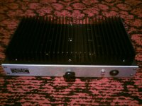
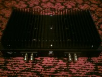
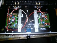
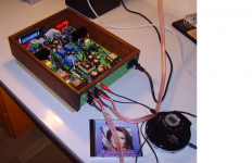
Hi,
this is my ACA with 1.6A bias current. I have made my own PCB, which has B1 buffer implemented. Amplifier is meant to be for PC. I am using old Tesla ARS 8104.54 4Ohm 15W, 88dB speakers. It sounds great. With ambient temperature 22 Celsius, heatsink is 45 Celsius. Heatsink could be little bigger, but it is OK. With 24V power supply (compared to 19V) it sounds even better, but heatsink gets too hot.
Thank you Nelson Pass!
Attachments
Gentlemen, from time to time my best DIY-friend and I like fooling around with DIY!
This time, this winter, we want to implement an "Active Speaker Concept".
"Active" means: my friend owns a DSP (having crossovers, attenuation, ...) and likes to connect it to his 3-way speaker.
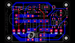
I will of course support him and will give him fully assembled ACA#1 - PCBs (my layout - image1) ) for his tweeters and his mid-tone chassis (is this the correct translation?).
For the bass we like and use ClassD-amplifiers like the L25D (image 2).
The ACA#1s and the ClassD will be built in separate cases, shielded from one another by a Mu-Metall layer.
Are we on the right way or do you instantly say: " ... no way to go ...".
Best regards - Rudi_Ratlos
This time, this winter, we want to implement an "Active Speaker Concept".
"Active" means: my friend owns a DSP (having crossovers, attenuation, ...) and likes to connect it to his 3-way speaker.
I will of course support him and will give him fully assembled ACA#1 - PCBs (my layout - image1) ) for his tweeters and his mid-tone chassis (is this the correct translation?).
For the bass we like and use ClassD-amplifiers like the L25D (image 2).
The ACA#1s and the ClassD will be built in separate cases, shielded from one another by a Mu-Metall layer.
Are we on the right way or do you instantly say: " ... no way to go ...".
Best regards - Rudi_Ratlos
Attachments
Last edited:
is it right, amp (after bias mod) sucks about 35W per channel, so 70W whole amp and therefor a at least 120VA /2x15V Trafo is to be used?
how much uF did you use in the PSU?
thanks in advance,
stefan
Yes you are right. Why don´t you use laptop PSU? It is cheap, light, efficient and gets the job done.
- Home
- Amplifiers
- Pass Labs
- Amp Camp Amp - ACA