and what is about the russian SIT´s? 2P926A?
L'Amp and Vfet amplifiers are made with Sony transistors.
DiyAudio Store and Papa in near future give possiblity for Diyers
to buy kit with pcb's
")
Acronman have some 2SJ28 we can buy
( reverse polarity -+ )
good news they are perfect for all Mr. Rothacher topologys :
with bulbs, thick film resistors, 193 V hammond inductors or CCS.
Mr. Pass announced new single-ended topology for this 2SJ28 and write
generously for us who try 2SJ18 | 2SK60.
So why search for diy project without schematics and not verified
& working amplifiers from more experienced designers ??
We can find this great Sony vfet's ( and please don't cry is too late in 2016 )
or buy kit this amplifiers are real SUPER Diy projects WORKING and VERIFIED.
All sit's are virtualy interesting if you can design amplifiers even more
example 2SK77 from Yamaha but that apriopriate for another thread
Greetings
... I´m in negotiations with the purchase of 20 pieces 2SK180 (23€ for one piece). I owned it already virtually...
Hi jps1964,
I have got 2SK180s with serial number 1Y... and 1Z... before from multiple sources, and they all turned out to be bad (as a triode). It doesn't mean all 2SK180s with these serial numbers are bad, just that there are at least some bad samples out there. I would try to negotiate a return/refund policy with the seller, though you need to have the means to measure if they're good.
I've got a sizable stash of 2SK180s lately, don't have a full box to spare but would be happy to off-load a few pairs, PM me if you're interested.
It depends on the model of CCS. Models that use BJT for the voltage reading across the MOSFET source resistor (like most of the circuits recommended by Nelson Pass and others, and the last "inverted polarity" proposition some posts ago) tend to be stable when the reading transistor is away from the hot areas, i.e., away from the power resistors or power MOSFETs or sinks. The source resistors can influence the current temp. stability, so it is recommended to use models that are recommended in the project. The MOSFET tempco, in these circuits, will not influence the current.... and whats about the compensation of the temperature drift in the CCS?
Models using depletion MOSFETs will follow the thermal coefficient of the device chosen for the role.
+ bias, probably adjustable from 3 to maybe 6 or 7V after some regulator, like in proposed project from earlier posts. If you use an heavy filtered bias supply (big caps), they slowly rise the voltage, reducing/nulling the start-up thump.... what would be the voltage range for +BIAS, supply voltage around -36VDC?
Is good to regulate the bias if you use the CCS version.
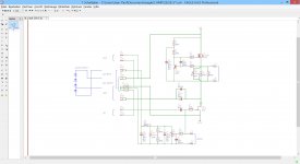
The schema is somewhat difficult to read, so if I made some mistake about component code, please advise:
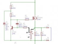
The R12 is for adjusting the CCS, I think... Since this is an hi-current node, is good to use an power rheostat or various fixed resistors for jumping/selecting the current (I used fixed resistors). If you use an rherostat is better to use some series resistor for limiting the adjustement at safe current levels (eg. using 1R/5W for R6 and R7, and making R12 an 10R/5W rheostat with 1R/5W or 0R82/5W in series). This will limit the maximum current.
A little 2 tips:
1 - For fine bias adjusting, you can put an 2k2 res in series with R9 bias potentiometer (I think) in negative side/pin, and in series with positive pin some 2k2 to 4k7 (is better to check in practice since I only gess-estimate the values without calculations).
2 - For low/none power-on thump, you can made the C5 with 4700µF.
@DIYBras
can you check please?
lalala
Attachments
For Zen Mod option the potentiometer can be low power, conventional type (excellent idea from Zen Mod, by the way!)@DIYBras
Thanks!
@Zen Mod
Thanks! Wattage for both? I have a 2W potentiometer type MCU from TE Connectivity...
The 2W pot can be used if you have at hand
Last edited:
that idea is everywhere in Pass forum , either as Zen Amount Pot (ratio of modulation) or as biasing setting
calc source resistance for minimal intended Iq , move wiper up to source
if you need to increase Iq , fiddle with pot
resistor in series with pot is just to put some boundary to max Iq and increase amount of fine setting
as drawn (47R fixed + 22R** pot), you can have effective source resistance (strictly speaking of Iq setting ) in range of 0R22 to 0R33
**20 or 22 or 25R , dunno what's exact standard
edit:
so , for R6 (ref to pic in post #2234) , if source resistance is 0R33 , effectively in range of 0R22-0R33 , Iq can be set in range of 2 - 3A (0V65/Rs)
in case of 0R47 for Rs , effectively 0R313-0R47 , Iq can be set between 1A38 to 2A07
that's pretty close , even if some are using 700mV as BE voltage reference
however , not changing much
Last edited:
- Home
- Amplifiers
- Pass Labs
- L'Amp: A simple SIT Amp