Grounding and Wiring
Hi Andrew and Jan,
thank you very much for your quick replies.
Quote: You have connected the input RCAs to Chassis. Remove this connection.
I have removed the RCA input connection as requested. Does this mean that there will be no connection to chassis ground?
Quote: You have connected the vol pots to Power Zero Volts. Remove this connection.
I do not really understand which connection I should remove. I have already amended the the connection between the volume pot and chassis.
Michael
Attachments
I have bought a number of the super regulator boards and they work great...
My question is...I needed jut the positive boards...so I have a few negative boards....
In a separate application, where I just need +12 volts...can I use the negative board and reverse the output connections??
My question is...I needed jut the positive boards...so I have a few negative boards....
In a separate application, where I just need +12 volts...can I use the negative board and reverse the output connections??
I have bought a number of the super regulator boards and they work great...
My question is...I needed jut the positive boards...so I have a few negative boards....
In a separate application, where I just need +12 volts...can I use the negative board and reverse the output connections??
You can do that if the connections from the transformer and rectifier etc have no ground connections; so you need a fully separate, floating secondary for this. Just float the whole shebang and ground the 'negative output' of the neg board and use the 'ground output' of the neg board as 'positive supply'.
Jan
I think this is what he means.
I think the ground wires on your head-amp board power supply ground should be removed from your potentiometer grounds and output jack grounds. Then tie the potentiometer ground to the signal in ground on the pcb and tie the head-amp output ground to the output jack ground on the pcb.
These being the signal in and ground from your potentiometer.
Connecting the input jack ground to chassis ground provides a path for a ground loop.
If you connect your potentiometer ground directly to the power supply input ground it would provide a noisier connection point as more current is flowing in this area. It's better to connect it to the input ground pad is there is little current/noise in this area.
Guys if any of my assumptions are wrong please correct me.
Quote: You have connected the vol pots to Power Zero Volts. Remove this connection.
I do not really understand which connection I should remove. I have already amended the the connection between the volume pot and chassis.
I think the ground wires on your head-amp board power supply ground should be removed from your potentiometer grounds and output jack grounds. Then tie the potentiometer ground to the signal in ground on the pcb and tie the head-amp output ground to the output jack ground on the pcb.
The input socket has two wires. Those two wires feed the vol pot.
The vol pot has two output wires. Those two wires feed the two input pads of the mono PCB.
These being the signal in and ground from your potentiometer.
Connecting the input jack ground to chassis ground provides a path for a ground loop.
If you connect your potentiometer ground directly to the power supply input ground it would provide a noisier connection point as more current is flowing in this area. It's better to connect it to the input ground pad is there is little current/noise in this area.
Guys if any of my assumptions are wrong please correct me.
I think the ground wires on your head-amp board power supply ground should be removed from your potentiometer grounds and output jack grounds. Then tie the potentiometer ground to the signal in ground on the pcb and tie the head-amp output ground to the output jack ground on the pcb.
These being the signal in and ground from your potentiometer.
Connecting the input jack ground to chassis ground provides a path for a ground loop.
If you connect your potentiometer ground directly to the power supply input ground it would provide a noisier connection point as more current is flowing in this area. It's better to connect it to the input ground pad is there is little current/noise in this area.
Guys if any of my assumptions are wrong please correct me.
I think you got it nailed.
Jan
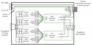
Follow RCA Right.
It has two signal wires: green and black.
These two wires connect to the vol pot.
The vol pot has two output wires.
One goes to Vin and the other goes to the Power Zero Volts.
The green Vin connection is correct.
The Black should be along with the Green. Instead it goes in a loop to 0V
Where at the head amp PCB is the connection to return the Signal back to it's source?
The connection back to the vol pot is missing.
Now repeat the exercise for the Left RCA.
This ends up at the headphone GND. So too does the Right RCA.
You have a BIG LOOP in the signal wiring from input RCAs to heaphone GND.
Use a pair of interconnects to a source and at that source you have a common ground. Now you have an even bigger loop and much of it is the Black Signal wire. This will pick up interference and ADD that interference to the signals. The headphones will hum.
You need to get the PSU Zero Volts out of the signal wiring.
You need to keep the signal wiring close coupled throughout their length to minimise the loop area.
... thank you very much for all your input!
I will prepare a new image that incorporates your suggestions and comments. Furthermore, I found an article in the audioXpress June 2013 'HighQualityPreamp' that shows a wiring and grounding scheme which seems to be relevant 'HighQualityPreampAXJun2013.pdf'.
Michael
I will prepare a new image that incorporates your suggestions and comments. Furthermore, I found an article in the audioXpress June 2013 'HighQualityPreamp' that shows a wiring and grounding scheme which seems to be relevant 'HighQualityPreampAXJun2013.pdf'.
Michael
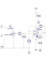
It is critical to look at how the signal return (I avoid 'ground'; helps to keep thoughts clear!) is carried to the amp input. It helps to think of ALL amps as differential - your amp amplifies the difference between the hot signal line and it's return. It does NOT just amplify 'input signal'. As Bruno Putzeys pointed out, a voltmeter always has TWO probes, just as an amp input always is differential.
So the question becomes: what are the two points at the amp input that gets amplified? That is where you connect the cable from the pot.
One of these points is clear - it's the 'signal input'. But what's the other? Certainly not the PSU ground at the other end of the board.
Jan
So the question becomes: what are the two points at the amp input that gets amplified? That is where you connect the cable from the pot.
One of these points is clear - it's the 'signal input'. But what's the other? Certainly not the PSU ground at the other end of the board.
Jan
Wiring and Grounding
... in the attachment there is now the input stage of the head amp and the new grounding and wiring image.
The return reference point is now near the input return - although drawn differently. The wiring will be done either with twisted interconnects or shielded cables. There is now a dedicated return for the pot and the input signals are 'treated' to be 'differential' - I hope I got this right. The return for the PSU and the signal will not be connected on the PCB itself - PCBs are not ready so far - but rather at the reference return point.
I hope this makes any sense.
Michael
Attachments
Last edited:
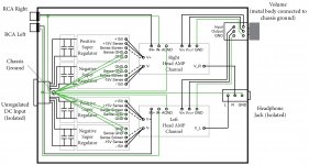
The schematic on the left seems OK, but on the right you've gone back to connecting signal return to chassis - why?
The whole wiring around the pot, which looked sort of OK before now seems all wrong.
Why connect Vout to the pot - isn't Vout the amp output?
The only pot stuff that was off in post 601 was the signal return; that should not be connected to supply center but to 'agnd' at the bottom of C103/R103.
Jan
Last edited:
... I am little bit confused. Should there be a connection to the chassis or not? If so, what should be connected to the chassis?The schematic on the left seems OK, but on the right you've gone back to connecting signal return to chassis - why?
Vin, Vout and GND is meant to be the pot's in, out, and GND in the schematics I2, O2 and G2. V_L and V_R are the amps 'VOUT' - sorry for making this a bit confusing.The whole wiring around the pot, which looked sort of OK before now seems all wrong.
Why connect Vout to the pot - isn't Vout the amp output?
Michael
Last edited:
... I am little bit confused. Should there be a connection to the chassis or not? If so, what should be connected to the chassis?
Vin, Vout and GND is meant to be the pot's in, out, and GND in the schematics I2, O2 and G2. V_L and V_R are the amps 'VOUT' - sorry to make this a little bit confusing.
Michael
But before you had the input wiring going to the pot, and then from pot to board. That was OK. Don't connect signal return to the chassis. Just take the two wires from the pot, wiper to board 'Vin' and bottom of the pot (which is also the return wire from the (insulated!) input RCA) to bottom of C103/R103. Much simpler than you think ;-)
Jan
Jan
I have been making this point for some years and repeating it on this Forum very many times. But the message is not getting to those that need it most.It is critical to look at how the signal return (I avoid 'ground'; helps to keep thoughts clear!) is carried to the amp input. It helps to think of ALL amps as differential - your amp amplifies the difference between the hot signal line and it's return.
Treat every CIRCUIT as a sole source plus receiver with a TWO WIRE connection from Source to Receiver.It does NOT just amplify 'input signal'. As Bruno Putzeys pointed out, a voltmeter always has TWO probes, just as an amp input always is differential.
So the question becomes: what are the two points at the amp input that gets amplified? That is where you connect the cable from the pot.
One of these points is clear - it's the 'signal input'. But what's the other? Certainly not the PSU ground at the other end of the board.
Jan
Strictly maintain that two wire connection with minimal loop area (twisted pair, or coax, or screen twisted pair) all the way and take care at the ends/terminals to maintain that LOW LOOP AREA.
Get ALL the circuits to meet that guidance.
Then look for the last few reference connections shown in the schematics and add these in. One to look for is the signal input circuit to the speaker output circuit. This needs a common voltage reference.
Read Leach's Low Tim paper, where he specifically refers to this reference and provides TWO routes, a low impedance route and a long (high impedance) route.
You need to recognise that the vol pot is a Jekyll and Hyde.... I am little bit confused. Should there be a connection to the chassis or not? If so, what should be connected to the chassis?
Vin, Vout and GND is meant to be the pot's in, out, and GND in the schematics I2, O2 and G2. V_L and V_R are the amps 'VOUT' - sorry for making this a bit confusing.
Michael
It behaves as both Source and Receiver.
From the RCA/Phono inputs the vol pot behaves as the receiver.
Wire the source to the receiver. Ignore all else do this the simplest way with least LOOP AREA.
For the h/amp PCB the vol pot behaves as the source.
Wire the source to the receiver and ignore all else. Again maintain least LOOP AREA.
Repeat for the other channel.
You now have FOUR circuits wired up.
Only 10 or 20 to go.
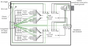
... ok.But before you had the input wiring going to the pot, and then from pot to board. That was OK.
This time the input wiring is going to the blocking cap C101 and then directly to the pot's in (Pin) and then through the pot's out (Pout) back to R101. The pot's GND (PGND) will be connected as recommended to C103/R103.
... ok. This means the chassis will only have connection to the metal body of the pot.Don't connect signal return to the chassis.
Michael
Attachments

Last edited:
the input offset of the h/amp is fed straight to the vol pot wiper.
You must AC couple from vol pot to amplifier.
Why have you moved from vol pot before the h/amp to this new arrangement?
Does the 134 datasheet give any warnings about impaired performance when pins 1 & 8 are connected by the output offset pot?
If it's like any other VFA opamp then you will get poorer performance.
Sort the output offset at the inputs, not by unbalancing the drain loads inside the opamp.
Last edited:
... ok.
This time the input wiring is going to the blocking cap C101 and then directly to the pot's in (Pin) and then through the pot's out (Pout) back to R101. The pot's GND (PGND) will be connected as recommended to C103/R103.
... ok. This means the chassis will only have connection to the metal body of the pot.
Michael
You'r moving away. Your 1st drawing was all spot on except the pot to board. Don't change everything all the time. Stay with what is correct and you ONLY had to change bottom pot to board.
In post # 601 the ONLY change to make it perfect is disconnect bottom pot to power supply center and reconnect bottom pot to bottom C103/R103. Done.
Jan
Last edited:
... ok I will move C101 after the potYou must AC couple from vol pot to amplifier.
... there is no explicit warning they just state that trimming is normally not needed. Would you recommend to remove P101?Does the 134 datasheet give any warnings about impaired performance when pins 1 & 8 are connected by the output offset pot?
If it's like any other VFA opamp then you will get poorer performance.
Michael
You'r moving away. Your 1st drawing was all spot on except the pot to board. Don't change everything all the time. Stay with what is correct and you ONLY had to change bottom pot to board.
In post # 601 the ONLY change to make it perfect is disconnect bottom pot to power supply center and reconnect bottom pot to bottom C103/R103. Done.
Jan
Thank you Jan this suggestion is very helpful!!
Since this is my first real diy project I really appreciate your help and guidance.
I will prepare a new schematic (based on # 601) and an image of the wiring and grounding.
Michael
- Home
- The diyAudio Store
- Super Regulator