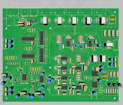
PDF quality sucks. It is an evaluation PCB , longer than needed traces.
A bigger "footprint".
You like the ESS ? I know it's 32- bit ... so what ? It all comes down to
the output buffer - ha ha , they even have the lowly 5532 as a choice.
All that 32--bit goodness getting puked out of a 20 year old IC !
OS
I think ESS don't have other choice than use 5532, because they don't make opamp.
All depend of the amp.Should a headphone amp have a zobel or output inductor?
Zobel is a question of stability.
Output inductor is not necessary because cable will be very short, so no fear of capacitive load, but recommended to block RFI returns in the feedback.
I myself have never seen a zobel used for a headphone amp.
One suggestion is to simulate the LineAmp with a load that better represents the real life device. Even sim into a large C and see what happens. So what headphones does everyone use? I do not have any that I consider any good.
One suggestion is to simulate the LineAmp with a load that better represents the real life device. Even sim into a large C and see what happens. So what headphones does everyone use? I do not have any that I consider any good.
I've had to switch to a larger single board design. The modular design was sprawling out too far with the large board to board connectors required to make it work. Here is the latest schematic and boards in progress.
I know Rsavas doesn't like the shunts on the last page of the schematic for the 15 - 5V conversion. OS, can you look at this and give me your opinion? Would you prefer to go a different direction with them?
I'm also looking for direction on the output of the linestage. I've set the output relays up with separate series 1 watt resistors for the line out and the headphones out to attenuate the power levels. There is also 1 watt resistors to ground to keep a load on the output of the linestage when output relays are open. Are these required? These relays will open every time there is a change in the input selection so there is no popping as relays switch.
Attachments
Hi Jeff,
Looking good.
Those power name nets = little hard to follow
You will need a compensation cap for ne5534a in positions U101,102. It is optional depending on the device, but it is needed for a ne5534a, as it is not unity gain stable. Just like U401 and the other I/V opamps. yes there is a cap across the feedback R so that would work the same, I guess, if it is chosen correctly.
You will need a AC present/fail detector, similar to what Valery V. has used on his protection design. A simple opto-coupler will work as well. This should be put on the power supply pcb and the open collector should go to a pullupR and a input port pin on the mcu.
Lots of use of regulators and ferrite beads. The series shunt/tl431 is okay. The pga23xx have excellent psrr. it is the pcm1794a that has no spec for psrr on the +5V, so this is the device requiring the super low noise.
Looking good.
Those power name nets = little hard to follow
You will need a compensation cap for ne5534a in positions U101,102. It is optional depending on the device, but it is needed for a ne5534a, as it is not unity gain stable. Just like U401 and the other I/V opamps. yes there is a cap across the feedback R so that would work the same, I guess, if it is chosen correctly.
Use the pga2311 mute feature, so you have the s/w mute the part or lower the gain when you do a source change. The only mute relay that should be required is on the output of the linestage/headphone buffer. This is to prevent power-up/down mute.These relays will open every time there is a change in the input selection so there is no popping as relays switch.
You will need a AC present/fail detector, similar to what Valery V. has used on his protection design. A simple opto-coupler will work as well. This should be put on the power supply pcb and the open collector should go to a pullupR and a input port pin on the mcu.
Lots of use of regulators and ferrite beads. The series shunt/tl431 is okay. The pga23xx have excellent psrr. it is the pcm1794a that has no spec for psrr on the +5V, so this is the device requiring the super low noise.
I do not think so. The pga2311 will do the attenuating of volume. The lineamp is stable with no load. Actually the feedback network is part of the load.I've set the output relays up with separate series 1 watt resistors for the line out and the headphones out to attenuate the power levels. There is also 1 watt resistors to ground to keep a load on the output of the linestage when output relays are open. Are these required?
I'll add the caps on the op amps. I'm still trying to figure out how to tell if an op amp is unity gain stable from the data sheet. It says unity gain bandwidth to 10MHz. I see they list some cap values with their 10MHz test conditions. Is that the indicator?Hi Jeff,
Looking good.
Those power name nets = little hard to follow
You will need a compensation cap for ne5534a in positions U101,102. It is optional depending on the device, but it is needed for a ne5534a, as it is not unity gain stable. Just like U401 and the other I/V opamps. yes there is a cap across the feedback R so that would work the same, I guess, if it is chosen correctly.
Use the pga2311 mute feature, so you have the s/w mute the part or lower the gain when you do a source change. The only mute relay that should be required is on the output of the linestage/headphone buffer. This is to prevent power-up/down mute.
You will need a AC present/fail detector, similar to what Valery V. has used on his protection design. A simple opto-coupler will work as well. This should be put on the power supply pcb and the open collector should go to a pullupR and a input port pin on the mcu.
Lots of use of regulators and ferrite beads. The series shunt/tl431 is okay. The pga23xx have excellent psrr. it is the pcm1794a that has no spec for psrr on the +5V, so this is the device requiring the super low noise.
I do not think so. The pga2311 will do the attenuating of volume. The lineamp is stable with no load. Actually the feedback network is part of the load.
Linuxworks has written the software to work with a relay fired resistor network for volume so the output relays are his muting. It looks like a neat design but the clicking on volume change through my Klipsch would likely blow me out of my chair!
 He's also got the software written for PGA with the mute pin connected so it may possibly do both.
The only other preamp/headphone amp I have built so far is Dadods MK2 and he had different resistors in series with each output on that. OS and I had talked about possibly needing to do something like this earlier. I'm not sure if he's done some simulating for this or not. I'd love to loose those huge resistors if possible.
The opamp datasheet will tell you if it is unity gain stable or not. Most of the new opamps are unity gain stable and if the d/s not saying anything, it infers unity gain stable. You can also look at the phase margin/vs gain graphs too.
Control of WM8805?
So far I only see h/w control and no s/w control! You drew the nets but they go nowhere, that I can tell = one pin nets. You really should have a way to have s/w control if you want to use the other spdif ports. One way or the other, since your i2c and spi are all 5V logic levels you will need a level converter.
You already have sudo spi using U103, so all you need is a level translating buffer and use a spare PCF8574 pin as your SS(slave select) for U401(WM8805)
I'm running the WM8805 as hardware for now. I'm going to need to add a small daughtercard on top of the DAC board for LED interface and to add a buffer for the extra relay at the PGA input. All WM8805 and PCM1794 options and Data connections connect to the daughtercard as well. That's what the four screw holes are for on the top left of the board. I hit my 1000 pin limit in DipTrace so they are connected by rows of Vias. I don't have a good path to run the PGA controls directly to it or they would be going there as well. As is there are vias available to jumper wire to it if needed. I'd like to do a little rearranging of those vias to form a pin header as well.The opamp datasheet will tell you if it is unity gain stable or not. Most of the new opamps are unity gain stable and if the d/s not saying anything, it infers unity gain stable. You can also look at the phase margin/vs gain graphs too.
Control of WM8805?
So far I only see h/w control and no s/w control! You drew the nets but they go nowhere, that I can tell = one pin nets. You really should have a way to have s/w control if you want to use the other spdif ports. One way or the other, since your i2c and spi are all 5V logic levels you will need a level converter.
You already have sudo spi using U103, so all you need is a level translating buffer and use a spare PCF8574 pin as your SS(slave select) for U401(WM8805)
Attachments
Last edited:
Should the WM8805 be controlled from a spare pin on a PCF8574 or should it connect directly to I2C?
Is an ISO1540 what I am looking for to do the voltage conversion? http://www.ti.com/lit/ds/symlink/iso1541.pdf
Is an ISO1540 what I am looking for to do the voltage conversion? http://www.ti.com/lit/ds/symlink/iso1541.pdf
You can not not connect wm8805 to the i2c bus used for PCF8574, as it is a 5V logic level and it is not tolerant.
wm8805 s/w control can be either i2c or spi depending on reset pin strapping.
ISO1540 is one option, NXP makes non-isolating i2c logic level converters.
I do not think you require galvanic isolation for the wm8805.
wm8805 s/w control can be either i2c or spi depending on reset pin strapping.
ISO1540 is one option, NXP makes non-isolating i2c logic level converters.
I do not think you require galvanic isolation for the wm8805.
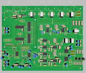
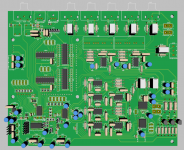
I've updated the schematic. I've removed the resistors at the outputs, added two outputs from U103 to the daughtercard connections, and have added an optional I2S switch for another I2S input.
I've got a daughtercard designed for running in hardware mode with the Arduino front end. It has indicators for relay operation and a driver for bi-coloured LEDs to indicate flagged functions of the WM8805(lock, non-audio data, ect.). I thing it would be better to design different optional daughtercards for different controls. In software mode the bi-coloured LEDs would br useless. The Arduino controls can be left unpopulated and all relays and devices can be controlled from the daughtercard connections.
The PC board is layed out. It just needs the silkscreen fixed up yet. The only part I see possibly being an issue is the relay coil traces running under the input caps and between the buffers. As is the relays are latching so there will only be current flow present while inputs or outputs are switching so I don't think there's much possibility of inducing noise from them.
Attachments
U341,342(GPIF...) should have 104 mlcc caps at the power pins!
It is the transients that get coupled, even if it is momentarilly it can be heard in sensitive ckts. Running digital signals in an analog only area is in principle a no-no. If no other option, use ground plane shielding of the digital signals.
Well I guess the proof will be when you test it out butThe only part I see possibly being an issue is the relay coil traces running under the input caps and between the buffers.
It is the transients that get coupled, even if it is momentarilly it can be heard in sensitive ckts. Running digital signals in an analog only area is in principle a no-no. If no other option, use ground plane shielding of the digital signals.
Good catch! I missed those caps.
I don't see another way to power the relays without running digital traces through the analogue section without external wires. That's the crappy part about relays switching analogue. Is a digital ground plane a good idea under analogue? In a normal circuit I wouldn't think twice, but analogue layout is fairly new to me.
I don't see another way to power the relays without running digital traces through the analogue section without external wires. That's the crappy part about relays switching analogue. Is a digital ground plane a good idea under analogue? In a normal circuit I wouldn't think twice, but analogue layout is fairly new to me.
- Status
- This old topic is closed. If you want to reopen this topic, contact a moderator using the "Report Post" button.
- Home
- Source & Line
- Analog Line Level
- Pitchfork pre-amplifier