Thanks for the info. I want the switching to be automatic. no knobs to turn or switches to flip. Is this passible with the passive line selector. a how to do guide would be much appreciated. I have a soldering iron but i'm not into electronicsif I know what parts to do and how to solder them I can manage that. Thanks.
There are several ways to do it
best but most advance would be something like that
Making a passive mixer. (Page 1) - Other Hardware - Forums - ChipMusic.org
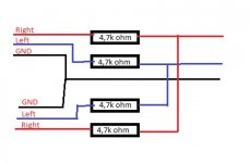
But I guess it should be also possible to bridge all GND's and add a 4.7k ohm to each L/R channel and also bridge them after the resistors... Look at attatchment if you don't understand
I'm not 100% sure as I'm also an electronics newbie but I guess it should work well and cost would be <2$Attachments
Last edited:
.
I am listening to my Lepai 2020a+ right now. I have it hooked to a pair of KLH speakers with Parts Express 2 way crossovers as an upgrade.
The 2020a+ has a 3 amp PS with a line choke. I replaced a few caps with good 10% caps. The big cap is now a 4700 uF 16v. Future upgrade is a 5A PS.
The sound running through windows equalizer on Rock, is Rocking right now. The sound is amazing for such a small amp.
I used to own a Sansui AU 717 and TU 5xx. The right side amp finally crapped out after 20 years of pushing 85w through Kenwood KL555's. I still have the Kenwood speakers hooked as primary to a Yamaha surround. They do not make amps like they did in the mid to late 70's.
So I feel qualified to say that the 2020a+ is an amazing piece of kit.
Despite what vomit eating Trolls would have you believe. Just a few mods make a big difference.
Tekko is a puke who wouldn't know a diode from a pimple on his nose.
Hi guys,
I've been reading through this whole thread (nearly finished!) and i note that when i see people replacing the input coupling caps, they're always using oversize film caps. Is there a reason to use something so physically large, and what do i search for to find some, or would 50V 2.2uF Wima caps or similar be fine?
I've been reading through this whole thread (nearly finished!) and i note that when i see people replacing the input coupling caps, they're always using oversize film caps. Is there a reason to use something so physically large, and what do i search for to find some, or would 50V 2.2uF Wima caps or similar be fine?
....or would 50V 2.2uF Wima caps or similar be fine?
Wima caps are not necessarily the best. There are quite a few options. Do check them out.
Wima caps are not necessarily the best. There are quite a few options. Do check them out.
Depends for what you refer them as "the best".
The red Wima caps will stop DC just like any other cap. I will go as far as to say that all the caps stop DC. In this application they will stop DC as any other cap so you can use them and they will work perfectly in this application!
Depends for what you refer them as "the best".
The red Wima caps will stop DC just like any other cap. I will go as far as to say that all the caps stop DC. In this application they will stop DC as any other cap so you can use them and they will work perfectly in this application!
Well, that's the problem. Just because Wima caps are used by major hifi manufacturers doesn't mean they are the best. But a lot of folks seem to think they are.
Has anyone tried the new "Lepy" variant? There is no plus in the model number and according to an ebay seller, the new model does not use the original Tripath. I wonder if they are inferior.
"the LP-2020A uses the lepy LP 2020 Audio Amplifier IC, and LePai LP-2020A+ uses the Tripath TA2020 IC.
The Lepy is the Chinese Trademark of Lepai in USA, and the Lepai LP-2020A+ has stop producing, the ones you saw online are the left ones, the factory announce another device called LP-2024A+, which is better than 2020A and 2020A+, and it is more expensive. All the new amplifiers from Lepai are branded Lepy now."
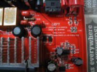
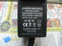
I just received my order from PE, the Lepai LP-2020A+ from ebay with free shipping. If you order direct from PE, you pay shipping. It has a black case and came with a 13.5v/3A wall wart. Leary about using it as I have a 12v/2A wall wart already. I powered it up with no input and it is very quiet. Opened it and it says Lepy on the red pcb. Photos to come tomorrow.
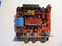
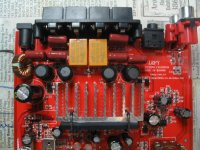
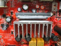
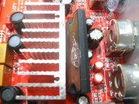
Connected the amp to an ipod and this amp sounds really good. Agree that the tone controls need reworking, but if not at full boost, they help some. I replaced the mis-matched .47uf caps in the output filter. They varied from .43uf to .49uf. I replaced them and matched up some .47uf caps. Removed the ceramic input caps, C31,C30 with 4.7uf film caps that I had on hand. Added a 4700uf to the 2200uf input DC cap. Added 1N5819 diodes on the outputs, just because I had them on hand. They fit nicely on the bottom of the pcb.
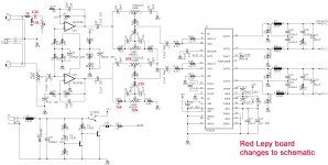
Marked up a schematic with values in RED of what is on my board.
Note that input is different and as close as I could trace, I found that the volume control is across pins 1 and 2 of the opamp, controlling its gain. That explains why people complain about a scratchy control. I did not have that effect, but sprayed it with Deoxit FaderLube as a future precaution.
Played amp for a while on my wood cabinet Minimus 7 speakers with 12v/2A PSU and it played very loud at 12 o'clock and clean. Connected the 13.5v/3A PSU and it played clean all the way to 2 o'clock. For my purpose, I am going to stick with the 12v PSU as an extra safety precaution. They vol pot case now has a ground wire to the ground plane on the PCB.
You can play it really too loud with the 13.5v PSU.
I am hoping that someone can come up with a schematic for this LEPY version, although I am not going to mod the tone control circuitry as the small smt parts are to difficult to access. Can't trace out the function of the second opamp.
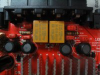
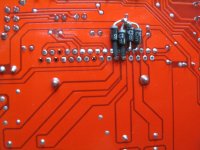
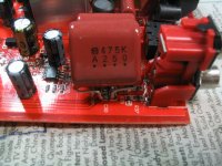
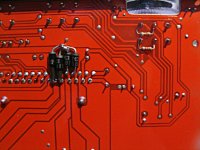
The chip in this amp is the TA-2020-020 by Tripath. Photos of chip with bad thermal past from factory. Relays are in the negative lead of the speaker terminals. They activate in about 3 seconds. The DC offset was 12mv right channel and 18mv left channel. Looks like someone has been reading this forum.
I found that all the solder joints were as good as it gets. No cold joints or bubbles. All shiny.
Marked up a schematic with values in RED of what is on my board.
Note that input is different and as close as I could trace, I found that the volume control is across pins 1 and 2 of the opamp, controlling its gain. That explains why people complain about a scratchy control. I did not have that effect, but sprayed it with Deoxit FaderLube as a future precaution.
Played amp for a while on my wood cabinet Minimus 7 speakers with 12v/2A PSU and it played very loud at 12 o'clock and clean. Connected the 13.5v/3A PSU and it played clean all the way to 2 o'clock. For my purpose, I am going to stick with the 12v PSU as an extra safety precaution. They vol pot case now has a ground wire to the ground plane on the PCB.
You can play it really too loud with the 13.5v PSU.
I am hoping that someone can come up with a schematic for this LEPY version, although I am not going to mod the tone control circuitry as the small smt parts are to difficult to access. Can't trace out the function of the second opamp.
The chip in this amp is the TA-2020-020 by Tripath. Photos of chip with bad thermal past from factory. Relays are in the negative lead of the speaker terminals. They activate in about 3 seconds. The DC offset was 12mv right channel and 18mv left channel. Looks like someone has been reading this forum.
I found that all the solder joints were as good as it gets. No cold joints or bubbles. All shiny.
Attachments
-
 lepy.JPG136.9 KB · Views: 346
 -
 relays.JPG108.4 KB · Views: 334
 -
 cap mods.JPG97.6 KB · Views: 154
 -
 5819pcb.JPG118.5 KB · Views: 135
 -
 new c31,c32.JPG124.5 KB · Views: 128
 -
 new .47uf.JPG157.1 KB · Views: 127
 -
 good paste.JPG153.9 KB · Views: 320
 -
 bad paste.JPG138.9 KB · Views: 328
 -
 psu.JPG130.7 KB · Views: 338
 -
 lp2020sch markup.jpg350.1 KB · Views: 175
Connected the amp to an ipod and this amp sounds really good. Agree that the tone controls need reworking, but if not at full boost, they help some. I replaced the mis-matched .47uf caps in the output filter. They varied from .43uf to .49uf. I replaced them and matched up some .47uf caps. Removed the ceramic input caps, C31,C30 with 4.7uf film caps that I had on hand. Added a 4700uf to the 2200uf input DC cap. Added 1N5819 diodes on the outputs, just because I had them on hand. They fit nicely on the bottom of the pcb.
Marked up a schematic with values in RED of what is on my board.
Note that input is different and as close as I could trace, I found that the volume control is across pins 1 and 2 of the opamp, controlling its gain. That explains why people complain about a scratchy control. I did not have that effect, but sprayed it with Deoxit FaderLube as a future precaution.
Played amp for a while on my wood cabinet Minimus 7 speakers with 12v/2A PSU and it played very loud at 12 o'clock and clean. Connected the 13.5v/3A PSU and it played clean all the way to 2 o'clock. For my purpose, I am going to stick with the 12v PSU as an extra safety precaution. They vol pot case now has a ground wire to the ground plane on the PCB.
You can play it really too loud with the 13.5v PSU.
I am hoping that someone can come up with a schematic for this LEPY version, although I am not going to mod the tone control circuitry as the small smt parts are to difficult to access. Can't trace out the function of the second opamp.
The chip in this amp is the TA-2020-020 by Tripath. Photos of chip with bad thermal past from factory. Relays are in the negative lead of the speaker terminals. They activate in about 3 seconds. The DC offset was 12mv right channel and 18mv left channel. Looks like someone has been reading this forum.
I found that all the solder joints were as good as it gets. No cold joints or bubbles. All shiny.
If you are going to keep the tone control, I also would recommend to upgrade the opamp for a LM4562.
After thinking about how the second opamp can go open loop if there is a a bad contact in the volume control, I added 82k resistors in parallel with the wiper and input terminal of the volume control. Anything around 100k would be fine, I just had 82k in to junk box. The volume control pot is 20k so, 82k has little effect on normal operation.
It's nuts that they control the gain with that opamp configuration. This version is nothing like the schematics I've seen posted.
I also removed the 1.5k dropping resistors in the blue LED circuit and used 4.7k in their place. Made the blue dial a little more reasonable to look at.
It's nuts that they control the gain with that opamp configuration. This version is nothing like the schematics I've seen posted.
I also removed the 1.5k dropping resistors in the blue LED circuit and used 4.7k in their place. Made the blue dial a little more reasonable to look at.
Attachments
Last edited:
The chip in this amp is the TA-2020-020 by Tripath.
Seriously Unlikely .. as it's a cheap clone... while the Lepai circuit bears NO resemblance to the Tripath Data sheet .
IF you ever heard a genuine Tripath Amp, this Lepai one would be in the trash bin.
Clone or not, it sounds good for what it is.. and that is ...a $30 amp. I have it driving my Realistic Minimus 7 wood cabinet speakers and using an Ipod as the source. With the EQ in the Ipod and the tone controls defeated, it is a nice little portable setup and serves my purpose.
Im getting one for my outdoor dayton speakers, Im reading about 4.2ohms on each channel with the 4 speakers outside by the pool.
My question is,
Has anyone landed the ideal PS? (12V....13.5V....16V)
Im lookin at this universal PS.
Selectable voltage "laptop" style power supplies 90 watt, 120 watt and 150 watt AC Switchmode power supplies, with user adjustable output 12V, 15V, 16V, 18V, 20V, 21V, 22V or 24V.
I read most use the 12V 2A laptop brick.. But I also know the amp can handle more voltage.
I confess, I did not read all 196 pages of this thread...lol
There are several ways to do it
best but most advance would be something like that
Making a passive mixer. (Page 1) - Other Hardware - Forums - ChipMusic.org
But I guess it should be also possible to bridge all GND's and add a 4.7k ohm to each L/R channel and also bridge them after the resistors... Look at attatchment if you don't understand
Hi. I'm back again with this project. Any electronics guru here to confirm the possibility of this, please?
To sum up my needs: I have two audio sources and one amp in my car. I want to use both sources with an automatic switching mechanism. The sound from source 1 will be muted through software I'm making. The 2 audio sources are: a computer sound card and a usb device (custom handsfree setup). When a call comes in the soundcard audio is muted. I just need to make the second audio souce sound go to the car amp over the same wiring. The car amp has only one input.
Another option would be to replace the car stock amp. Is this small amp good for a car setup?
My question is,
Has anyone landed the ideal PS? (12V....13.5V....16V)
Im lookin at this universal PS.
Selectable voltage "laptop" style power supplies 90 watt, 120 watt and 150 watt AC Switchmode power supplies, with user adjustable output 12V, 15V, 16V, 18V, 20V, 21V, 22V or 24V.
I read most use the 12V 2A laptop brick.. But I also know the amp can handle more voltage.
The protection circuitry in this amp will cut off at around 13.5V. Therefore, a 12V power supply is still the best choice. Most of us will go for at least 5A for extra headroom.
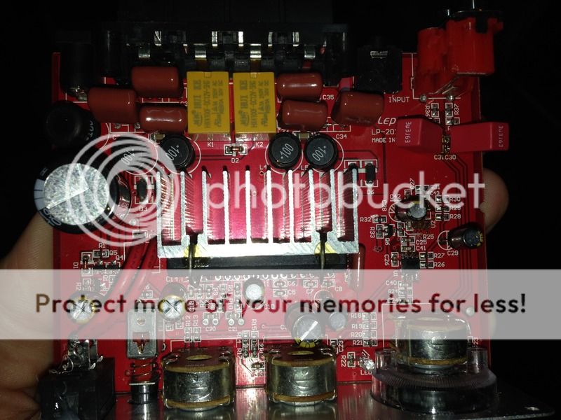
New surface mount caps on C20/C21???
Hi all. been reading...a lot...not sure if I missed my answers above.
1) I opened up my 202A+. Just above where C20 and C21 would go appear to be two surface mount caps. Nothing in the holes for C20/21. (See pic). The amp worked before I dug into it (ruined the opamp pads, will start a new project now that I've practiced on some refuse boards).
Any one else see this? They measure approx. 3uF in the board.
I assume I can remove these and put in replacement caps in the holes. Some one stop me if I'm wrong.
2) My board came with two 470uf caps and one 220uf cap. The parts lists I've seen call for two 220's and one 470. Did Lepai change their configuration, or put the wrong cap in?
3) What's the most popular replacement opamps these days? I know that's a huge debate and I'll read more above.
Thanks in advance.
Dave

An externally hosted image should be here but it was not working when we last tested it.
- Status
- This old topic is closed. If you want to reopen this topic, contact a moderator using the "Report Post" button.
- Home
- Amplifiers
- Class D
- Lepai T-Amp with TA2020