Hi, I have a question. I was wondering if this PSU would work for a standard F5 build. Until now I have had a CRC unregulated PSU running, it works nice and all, but I wanted to tinker a little bit more.
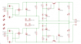
I have found the schematic in a zen article by NP but he used mosfets instead of the darlingtons. In LTSpice the schematic works great, almost no difference in ripple to my CRC which uses almost 10x as much capacitance.
The two SK129 are 63mm ones with 4.5K/W, which in normal operation (until class AB) means about 35K above ambient, or in huge overload configuration about 40K above ambient.
Attachments
Is it ok to put a 100nF cap across the thermistor between PS common and safety earth?
Seems like Rod Elliott suggests this component to be present in a ground loop breaker... why not here?
It's OK (unless it works worse). It may be that Rod feels that it will shunt
high frequencies better - I have seen it on some older receivers, where input
connector ground is shunted locally to chassis, even though there was a
wire elsewhere doing the same.

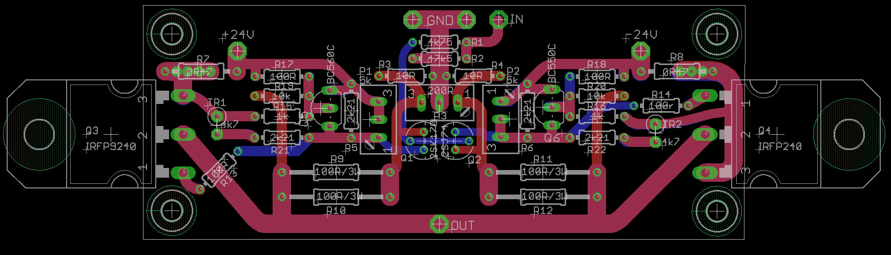
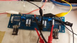
PCBs arrived, looking really well:

Thank you all for your support ! Will start soldering this evening.
I will have a few PCBs left, is it allowed to offer them to the community?
Help Please!
Hi at all!
For the second time my f5 v2 turbo burned!
I have noticed you that this happened because I connected at the input a tube preamp of my friend that unfortunately at turned off and on pulled out 144Vdc.
My F5 burned after a few seconds!
I must tell you that I thought that inserting in parallel to R2 47,5K two zener diodes connected in anti-series would have kept away of risk my amp but this did not happen unfortunately.
Now I must also tell you that by controlling which components are burned, I found that only the Power MOSFETs are burned.
It 'strange to find that both the protection diodes in the input ad also the FET 2SK170 / 2sj74 are safe, I expected to find them burned.
I would think that as an additional protection I would insert a capacitor input immediately after R1 1K as done by Nelson Pass Aleph series.
What do you think about that?
I know that in some way could deteriorate signal ...
But since I am now also sostiuendo the IRFP9240 / IRFP240 with the most beautiful and expensive ECW20N20Z / ECW20P20Z, I would not want to risk burning them in again.
Do you have any advice on the input capacitor to be taken?
Thank you in advance.
Antonio
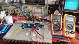
Hi all, I suspect to have a problem with my F5. After having checked the potentiometers I connected the three DMM and started it through a dim bulb tester. The voltage across the two 0.47R resistors is 0 but at the output I measure, relative to ground, a negative voltage equal to the negative supply (around -19 V with the dim bulb tester). This happens on both channels.
Is it normal to have such offset at the beginning of the bias adjustment?
Thanks!
Is it normal to have such offset at the beginning of the bias adjustment?
Thanks!
I made some more measures on one of the channels. Values are in the picture. The reduced supply voltage is due to the dim bulb tester. If I remove it, fuse blows.

I'm really a beginner in electronics but I would focus on the N channel mosfets. Right?
I will make some pictures as soon as I get back to the workbench.
I'm really a beginner in electronics but I would focus on the N channel mosfets. Right?
I will make some pictures as soon as I get back to the workbench.
No load on output, input not grounded.input grounded , no load on output ?
- Home
- Amplifiers
- Pass Labs
- F5 power amplifier