Upon further listening, with the much lower C2 (3.5uF) there is a maybe a bit more hum but its only noticable if I am right next to the speaker. If you look at Sheldon's thread on his 801 amplifier, you will see he used a C2 of 4uF and a C3 of 8uF
http://www.diyaudio.com/forums/tubes-valves/125488-loftin-white-801-amp.html - post #8 is the correct schematic I believe.
I agree that there is room to reduce the value of both capacitors without affecting hum to reduce "ultrapath" influence.")
Howeve I have not been able to hear any sonic difference whatsoever I have switched it back and forth a couple of times now and compared various test recordings that are typically difficult to reproduce. It seriously sounds neither worse nor better.
Maybe it will made a difference when I use the new transformers? I hope to try them out today!
http://www.diyaudio.com/forums/tubes-valves/125488-loftin-white-801-amp.html - post #8 is the correct schematic I believe.
I agree that there is room to reduce the value of both capacitors without affecting hum to reduce "ultrapath" influence.
Howeve I have not been able to hear any sonic difference whatsoever I have switched it back and forth a couple of times now and compared various test recordings that are typically difficult to reproduce. It seriously sounds neither worse nor better.
Maybe it will made a difference when I use the new transformers? I hope to try them out today!
Last edited:
Your thinking appears to be wrong. The ultrapath cap shorts the output stage AC current path directly to B+, and that's it. Of course, it's in the audio path. But it takes the PSU out of the audio path. It's also not in series with any other cap.
Of course! This is perhaps why I hear no sonic difference.
Of course the "ultrapath" capactor is as important as "Chb" in this topology.
Last edited:
Your thinking appears to be wrong. The ultrapath cap shorts the output stage AC current path directly to B+, and that's it. Of course, it's in the audio path. But it takes the PSU out of the audio path. It's also not in series with any other cap.
You guys do not understand what is basic principe of ultrapath capacitor.
Between ultrapath cap and last cap in PSU, MUST be choke or resistor.
I have read up on ultrapath once again (it has been ages since I did this) and believe this cap should not be referred to as an Ultrapath cap.
Rajko - you need to try to draw a loop (that goes through the OPT) to explain your point. You did not do that yet... Please see the diagram that Darius once drew to illustrate the point.
Rajko - you need to try to draw a loop (that goes through the OPT) to explain your point. You did not do that yet... Please see the diagram that Darius once drew to illustrate the point.
Attachments
Last edited:
I have read up on ultrapath once again (it has been ages since I did this) and believe this cap should not be referred to as an Ultrapath cap.
Rajko - you need to try to draw a loop (that goes through the OPT) to explain your point. You did not do that yet... Please see the diagram that Darius once drew to illustrate the point.
OK, tnx Ian.
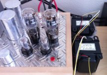
This afternoon I hooked up the J&K Output transformers. It was a great treat and I found it hard to turn the amp off this evening... J&K Audio Design
These are the "ALIS-5SE Ultimate" transformers. I have them on the 3.5k primaries. Here are the specs:
Power: 30W(20Hz) Single Ended
Bandwidth:
*Actual measured with 0 feedback
*300B: 9-70kHz +0/-1dB), 15-45kHz +0/-0.5dB
*2A3: 11-75kHz +0/-1dB), 17-50kHz +0/-0.5dB
Primary: 3.5K, 2.5K; Secondary: 0-4-8-16 Ohm
Pri. DCR: 82.5 Ohm(B-P2.5K); 97.5 Ohm(B-P3.5K)
Sec. DCR: 0.67 Ohm (0-16 Ohm)
Primary Inductance: 18H(@80mA, 20Hz, 5Vrms)
Primary Current: 65-85mA (100mA max)
Core: Special Mix Hybrid Cores - EI96
The first thing I notice is that upon starting up my amp, it stablizes quicker than with the little OPT's. The design is such that as the B+ comes up, there is some hum which soon dissapates. This all happens within a minute. This is exactly what I was expecting with superbly wound high quality ALIS OPT's, which is good!
The amp and my speakers are totally dead silent now too. Scary silent I would suggest... Only the glowing tubes give away that it is on. I have a dozen of these older golden dragon 2a3 tubes for testing purposes... Some test good but are actually a bit noisy or microphonic. You could hear the microphonic nature with the cheaper transformers immediately. Not with the new OPT's though! Any tube that tests good works well! This will be BLISS when I start to use NOS tubes... or maybe some recent production mess plate ones? hmmmmm
Now the SOUND.. omg... it's truly wonderful. So fully musical (please, no "full music" jokes). Not that the "test" transformers were bad, but the difference with the ALIS ones is profound. The bass is so FIRM. The sound stage is now so incredibly deep! Upper end is inspiring yet not tiring. I hear new transients out of recordings too. For example, I hear a chair creaking or a maybe a foot slipping on the floor and realized that I was looking at its "position" in my living room...
The sound actually got BETTER as I played more and more music this afternoon. I am never one to believe in any break-in factor - either something clearly works from the beginning or it's junk. But now after this afternoon I am thinking that they are even getting better over time.
Ok, I'm off my soap-box now. I have to do a complete new lay-out to fit these in, which will take me some time.
I hope to test and compare the Tango XE-20s later this week as well. I took them out of a previous project and they are now ready to go in this design. Too bad they are no longer in production....
J&K Audio DesignThese are the "ALIS-5SE Ultimate" transformers. I have them on the 3.5k primaries. Here are the specs:
Power: 30W(20Hz) Single Ended
Bandwidth:
*Actual measured with 0 feedback
*300B: 9-70kHz +0/-1dB), 15-45kHz +0/-0.5dB
*2A3: 11-75kHz +0/-1dB), 17-50kHz +0/-0.5dB
Primary: 3.5K, 2.5K; Secondary: 0-4-8-16 Ohm
Pri. DCR: 82.5 Ohm(B-P2.5K); 97.5 Ohm(B-P3.5K)
Sec. DCR: 0.67 Ohm (0-16 Ohm)
Primary Inductance: 18H(@80mA, 20Hz, 5Vrms)
Primary Current: 65-85mA (100mA max)
Core: Special Mix Hybrid Cores - EI96
The first thing I notice is that upon starting up my amp, it stablizes quicker than with the little OPT's. The design is such that as the B+ comes up, there is some hum which soon dissapates. This all happens within a minute. This is exactly what I was expecting with superbly wound high quality ALIS OPT's, which is good!
The amp and my speakers are totally dead silent now too. Scary silent I would suggest... Only the glowing tubes give away that it is on. I have a dozen of these older golden dragon 2a3 tubes for testing purposes... Some test good but are actually a bit noisy or microphonic. You could hear the microphonic nature with the cheaper transformers immediately. Not with the new OPT's though! Any tube that tests good works well! This will be BLISS when I start to use NOS tubes... or maybe some recent production mess plate ones? hmmmmm
Now the SOUND.. omg... it's truly wonderful. So fully musical (please, no "full music" jokes). Not that the "test" transformers were bad, but the difference with the ALIS ones is profound. The bass is so FIRM. The sound stage is now so incredibly deep! Upper end is inspiring yet not tiring. I hear new transients out of recordings too. For example, I hear a chair creaking or a maybe a foot slipping on the floor and realized that I was looking at its "position" in my living room...
The sound actually got BETTER as I played more and more music this afternoon. I am never one to believe in any break-in factor - either something clearly works from the beginning or it's junk. But now after this afternoon I am thinking that they are even getting better over time.
Ok, I'm off my soap-box now. I have to do a complete new lay-out to fit these in, which will take me some time.
I hope to test and compare the Tango XE-20s later this week as well. I took them out of a previous project and they are now ready to go in this design. Too bad they are no longer in production....
Attachments
Last edited:
OK, tnx Ian.
I promise to try what you suggested. Thanks for taking an interrest in this!
This afternoon I hooked up the J&K Output transformers. It was a great treat and I found it hard to turn the amp off this evening...
Thanks for making me aware of J&K Audio... I'm going to be in touch with them for the opt's on my next project. A lot of great reading on their website.
Great to hear denny. I had my L-W amp running this morning for a couple of hours then again in the evening. The J&K ALIS transformers are getting even more musical with time.
At the very beginning I had this deep soundstage, like music was coming from behind my speakers.... but after a few hours of playing it now moving forward in a lovely way. Still super deep when it should be, but now it is all over my living room too. Phenominal imagery. Had some esbjorn svensson trio on in the morning.. wow... its really just like when I saw them live. The percussion is crazy real now.. sustain sounds really like sustain... I could go on and on. Had some Bluegrass this evening - my youngest daughter plays guitar and she was simply mesmorized.
Now the bad news... I won't have time to make any changes to test the Tango's until this weekend. I'm off to the Netherlands for the next two days for work. Hopefully I can do some comparisons this weekend though.
Ian
Last edited:
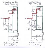
I had a few requests regarding designing this amplifier, so I will make some postings to help explain this circuit for beginners. If you are an experienced builder it will no doubt be boring (sorry). I won't claim that it will be all-encompasing, but hope to cover all the basics.
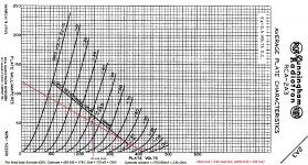
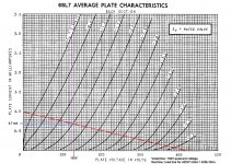
My first step was to decide upon a load line and operating point for the output tube (2a3). Looking at the RCA average plate curves for 2a3 is useful. I chose to use an output transformer with a primary impedance of 3.5k ohm - which is different than the RCA recommendations of 2.5k ohm. The reason I chose this is because I was willing to lose a bit of power and gain a more linear response.
You can even go higher than 3.5k if your speakers are sensitive, but be careful - a change in design changes operating points in this circuit, so some re-design might be necessary.
In the picture you see my 3.5k load line. It helps to have a bit of an idea about your power supply before you plot this line. I knew that I could build a DC power supply that could deliver around 420V for approx 100mA load from previous projects. I also knew that my power transformer from Thomas Mayer vinylsavor.blogspot.com had multiple secondaries in case I needed a different voltage (VERY useful)
I also knew that I would be doing fixed bias, so I could raise the cathode voltage to meet my design needs.
In any case, to plot the load line I just took 420V/3.5k Ohm to give 120mA. This is the red line on the plate curves graph.
From that point, I looked at my load line and considered where to best bias the 2a3. RCA suggests 60mA quiescent current, but I would like my 2a3's to last nice and long. I chose 50mA, which is what you will get if you bias at -45V. If you plot this point on the load line, you will see a plate voltage of 245V.
This means the Anode-Cathode voltage should be 245V, and my cathode should run quiescent at 420-245= 175V for 50mA. In order to run at 50mA, the grid has to be at -45V relative to the cathode, so this is 175-45= 130V.
For effective direct coupling and amplification, we will need to meet some very important conditions- The very first consideration for direct coupling will be that the anode of the input triode needs to be at about 130V. I will continue on this point in another post.
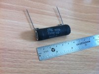
The cathode resistor needs to be around 3.5k ohm to hold the cathode at 175V at 50mA. If you do the maths, you will see that it needs to dissapate 175V*0.50A = 8.75 Watts of power. This current is constant, and dissapating it creates heat. Its a good rule of thumb to chose a good wirewound resistor that can dissapate 3x the power you calculate. I have attached a picture of a 25W 3500 Ohm wire-wound resitor I like to use.
to be continued...
My first step was to decide upon a load line and operating point for the output tube (2a3). Looking at the RCA average plate curves for 2a3 is useful. I chose to use an output transformer with a primary impedance of 3.5k ohm - which is different than the RCA recommendations of 2.5k ohm. The reason I chose this is because I was willing to lose a bit of power and gain a more linear response.
You can even go higher than 3.5k if your speakers are sensitive, but be careful - a change in design changes operating points in this circuit, so some re-design might be necessary.
In the picture you see my 3.5k load line. It helps to have a bit of an idea about your power supply before you plot this line. I knew that I could build a DC power supply that could deliver around 420V for approx 100mA load from previous projects. I also knew that my power transformer from Thomas Mayer vinylsavor.blogspot.com had multiple secondaries in case I needed a different voltage (VERY useful)
I also knew that I would be doing fixed bias, so I could raise the cathode voltage to meet my design needs.
In any case, to plot the load line I just took 420V/3.5k Ohm to give 120mA. This is the red line on the plate curves graph.
From that point, I looked at my load line and considered where to best bias the 2a3. RCA suggests 60mA quiescent current, but I would like my 2a3's to last nice and long. I chose 50mA, which is what you will get if you bias at -45V. If you plot this point on the load line, you will see a plate voltage of 245V.
This means the Anode-Cathode voltage should be 245V, and my cathode should run quiescent at 420-245= 175V for 50mA. In order to run at 50mA, the grid has to be at -45V relative to the cathode, so this is 175-45= 130V.
For effective direct coupling and amplification, we will need to meet some very important conditions- The very first consideration for direct coupling will be that the anode of the input triode needs to be at about 130V. I will continue on this point in another post.
The cathode resistor needs to be around 3.5k ohm to hold the cathode at 175V at 50mA. If you do the maths, you will see that it needs to dissapate 175V*0.50A = 8.75 Watts of power. This current is constant, and dissapating it creates heat. Its a good rule of thumb to chose a good wirewound resistor that can dissapate 3x the power you calculate. I have attached a picture of a 25W 3500 Ohm wire-wound resitor I like to use.
to be continued...
Attachments
since all is talking about dc coupled, i am not very confident about it.
been searching on internets about pentode driver, found none configuration like this (Schade)
also people are avoiding gridchokes like plague (why), bias stability is better than resistors
opinions on this one?
been searching on internets about pentode driver, found none configuration like this (Schade)
also people are avoiding gridchokes like plague (why), bias stability is better than resistors
opinions on this one?
An externally hosted image should be here but it was not working when we last tested it.
Part 2.
Now look at the 2a3 average plate curves above. You will see some violet lines. The middle line represents or quiecent point of 50 mA. The anode is around 420V, The cathode at 175V and the grid at 130V.
With this bias point and this load of 3.5k Ohm, we have a nice linear range where the AC signal can change the grid voltage. I marked this linear range as being from 180V to 310V on the graph (which in reality, referenced to ground it is 65v to 195V). This is about 130V AC peak-to-peak (p-p).
If our input signal is line level, it will probably be around 1.5V p-p. We will need an amplification factor of 130V/1.5V= 86.7 to get the most out of this range.
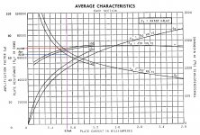
For a directly coupled amplifier, if you only want to use one input triode, then choices are limited. From the most common tubes, you can chose 12ax7 or perhaps 6SL7. I know there are other tubes out there, but to keep this simple I will just chose 6SL7. There is no reason why you could not use 12ax7 though.
We need the quiecent anode voltage of the 6SL7 to be at 130V. This means we need to drop from 420V to 130V. Some would argue that we also need a resistor-capcitor networ between the stages to block AC, but for the sake of simplicity lets just look at this drop of 290V.
A second consideration is our AC signal. We have 1.5V p-p, so our bias should really always be above this.
One more consideration is that we want the 6SL7 to operate in a region it is linear, and it must conduce some current.
I have plotted a possible load line in the attachment. It appears to meets our above requirements, but in my next post we will see that there is a problem with using this load line.
To be continued...
Now look at the 2a3 average plate curves above. You will see some violet lines. The middle line represents or quiecent point of 50 mA. The anode is around 420V, The cathode at 175V and the grid at 130V.
With this bias point and this load of 3.5k Ohm, we have a nice linear range where the AC signal can change the grid voltage. I marked this linear range as being from 180V to 310V on the graph (which in reality, referenced to ground it is 65v to 195V). This is about 130V AC peak-to-peak (p-p).
If our input signal is line level, it will probably be around 1.5V p-p. We will need an amplification factor of 130V/1.5V= 86.7 to get the most out of this range.
For a directly coupled amplifier, if you only want to use one input triode, then choices are limited. From the most common tubes, you can chose 12ax7 or perhaps 6SL7. I know there are other tubes out there, but to keep this simple I will just chose 6SL7. There is no reason why you could not use 12ax7 though.
We need the quiecent anode voltage of the 6SL7 to be at 130V. This means we need to drop from 420V to 130V. Some would argue that we also need a resistor-capcitor networ between the stages to block AC, but for the sake of simplicity lets just look at this drop of 290V.
A second consideration is our AC signal. We have 1.5V p-p, so our bias should really always be above this.
One more consideration is that we want the 6SL7 to operate in a region it is linear, and it must conduce some current.
I have plotted a possible load line in the attachment. It appears to meets our above requirements, but in my next post we will see that there is a problem with using this load line.
To be continued...
Attachments
I chose to use an output transformer with a primary impedance of 3.5k ohm - which is different than the RCA recommendations of 2.5k ohm. The reason I chose this is because I was willing to lose a bit of power and gain a more linear response.
Just as a note, I found that if you want to use a 3.5K OPT, and you can inrease your B+ a little, you could shoot for Ua=300V, Ia=49mA, Ubias=-58.5V.
Compared to the classic operating point, this should give you slightly less distortion, slightly more output power, and of course the higher damping factor.
Just be a little careful when your Ua starts to approach 450~500V during startup. Some tubes (NOS?) may not like it. A clever circuit / startup behaviour might alleviate this.
Part 3.
If we look at the proposed load line for our 6SL7 we see a very significant anode resistor of 420k. Our first thought might be that such a large anode resistor will be good enough. A general rule of thumb in building circuits with triodes is that the anode resistor should be 4 or 5 times greater than the plate resistance of the triode. But is it really good enough?
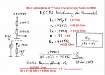
Without going into the theory too deep, we can use a formula to determine if our proposed load line will result in a linear frequency response. For physicists, feel free look up the work of physicist Hendrik Johannes van der Bijl (sometimes incorrectly attributed to german physicist Heinrich Georg Barkhausen).
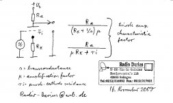
Darius describes this formula as the "triode amp characteristic" factor:
triode amp characteristic factor - sorry it is in german
As Sheldon has previously noted, this is just the ratio of the plate resistor, divided by the resistance of the tube at the plate. This ratio should be greater than 4 for good linearity.
In our example above, we actually only have a "triode amp characteristic" factor of 2 - which is nowhere good enough. See the attachements for how to easily determine this value.
What will this mean? Well, it will mean that the response will not be linear and it will definitely not sound good. I will go over alternative ways to address this problem in my next post.
to be continued...
If we look at the proposed load line for our 6SL7 we see a very significant anode resistor of 420k. Our first thought might be that such a large anode resistor will be good enough. A general rule of thumb in building circuits with triodes is that the anode resistor should be 4 or 5 times greater than the plate resistance of the triode. But is it really good enough?
Without going into the theory too deep, we can use a formula to determine if our proposed load line will result in a linear frequency response. For physicists, feel free look up the work of physicist Hendrik Johannes van der Bijl (sometimes incorrectly attributed to german physicist Heinrich Georg Barkhausen).
Darius describes this formula as the "triode amp characteristic" factor:
triode amp characteristic factor - sorry it is in german
As Sheldon has previously noted, this is just the ratio of the plate resistor, divided by the resistance of the tube at the plate. This ratio should be greater than 4 for good linearity.
In our example above, we actually only have a "triode amp characteristic" factor of 2 - which is nowhere good enough. See the attachements for how to easily determine this value.
What will this mean? Well, it will mean that the response will not be linear and it will definitely not sound good. I will go over alternative ways to address this problem in my next post.
to be continued...
Attachments
Just a quick question,
Why do you rely on the wiper of the volume pot to ground the grid of the first tube?
Regards
M. Gregg
Thanks for noting this. I must admit some laziness when drawing the schematic. It is of course best practice to bypass the volume control with a suitable (100k Ohm or higher) resistor. It is built this way in my prototype.
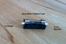
It is also very wise to use a B+ fuse on directly coupled amplifiers. In my prototype I have used a T150mA slow blow fuse. If the input 6SL7 were to stop functioning (fail or be accidentally pulled out during operation) the bias voltage could change and allow the 2a3 to run away.
This fuse will allow for one tube to run up to about 100mA for a short period of time before blowing. It might not save the 2a3, but it will save the output transformer.
Ian
Attachments
This fuse will allow for one tube to run up to about 100mA for a short period of time before blowing. It might not save the 2a3, but it will save the output transformer.
Ian
I bypass fuses in non safety critical DC applications with a high voltage polypropylene capacitor to quench the arc.
Its also interesting for those that say fuses have a "Sound" its bypassed..
Regards
M. Gregg
Last edited:
since all is talking about dc coupled, i am not very confident about it.
been searching on internets about pentode driver, found none configuration like this (Schade)
also people are avoiding gridchokes like plague (why), bias stability is better than resistors
opinions on this one?
I like pentodes, It appears to be your own design - did you build it already? Grid chokes are probably nice but last time I checked they cost significantly more than resistors and need space. I have used TVC's and Autoformers before as well, but they need space too so didn't use them here. I wanted to try this with parts on hand that were cheap.. and I only posted it because it worked far better than I had expected.
Of course nobody is saying you have to build dc coupled. I'm sure your amplifier sounds lovely despite the cathode by-pass and coupling capacitors.
Last edited:
I bypass fuses in non safety critical DC applications with a high voltage polypropylene capacitor to quench the arc.
Its also interesting for those that say fuses have a "Sound" its bypassed..
Regards
M. Gregg
I have never witnessed arcing or been able to discern any sonic influence.
Of course my B+ comes up nice and slowly since I rectify using TV damper diodes.
Best regards
Ian
- Status
- This old topic is closed. If you want to reopen this topic, contact a moderator using the "Report Post" button.
- Home
- Amplifiers
- Tubes / Valves
- My New Iron for Single Ended 2a3