Yes, might just be for a little less dissipation in the JFET, or more comfort about peak drain voltages.Do the LEDs just drop some DC voltage for the input FET dissipation? And hey they light up green.
I recall that discussion distantly, and I did some experiments on samples, but I don't think I got as far as incorporating such a driven substrate into a design. I do recall that the isolation of the gates of the 389 was more complicated than a simple reverse-biased diode, and also that the breakdown voltages gate-to-gate or gate-to-substrate were surprisingly high. I'm not sure how the Linear Integrated Systems equivalent parts compare.
Without any additional information, I suppose you could try biasing the substrate with a voltage that tracks the follower output, perhaps with a battery at least for the experiment. With a resistor in series you can preclude damage from excessive voltages.
I was exploring the possibility of using leakage to that substrate pin as a probe of temperature, but it was not promising iirc.
Brad
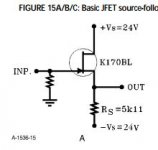
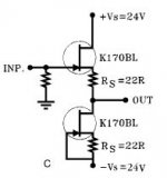
Brad, Thank you. I will try your tips and perhaps a few more things before I give up. FWIW, The circuits I tried were identical to those in borbelys article pt 2. table 15 a and c. In the case of the simple follower (a), the second jfet was either (i) left unused and floating , or (ii) wired up identically as a simple follower but driven with an antiphase signal. In all cases, i tied the substrate pin to the output and the results I found were pretty much identical (ie doing so increased dist dramatically & that is puzzling given what i understand of the dist mechanism). Anyway, will report back after i have time to play with this this some more...
Attachments
The New Mastersounds ---
https://www.youtube.com/watch?v=pgek3tGlCk4
Crank it up!
[www.newmstersounds.com]
THx-RNMarsh
https://www.youtube.com/watch?v=pgek3tGlCk4
Crank it up!
[www.newmstersounds.com]
THx-RNMarsh
(SS)?
Ah, Solid-State.
See the discussion group under "CFA Topology Audio Amplifies" to learn the real story.
THx-RNMarsh
But you were doing this with a 389?Brad, Thank you. I will try your tips and perhaps a few more things before I give up. FWIW, The circuits I tried were identical to those in borbelys article pt 2. table 15 a and c. In the case of the simple follower (a), the second jfet was either (i) left unused and floating , or (ii) wired up identically as a simple follower but driven with an antiphase signal. In all cases, i tied the substrate pin to the output and the results I found were pretty much identical (ie doing so increased dist dramatically & that is puzzling given what i understand of the dist mechanism). Anyway, will report back after i have time to play with this this some more...
But you were doing this with a 389?
Yes indeedy
TLO82s, LED Clippers a few other things haha,
Its real easy to modd/ blowtorch out some amps haha
that's insane amount of clipping/distortion to me though haha, I'm not even that much of a Metal guy some though haha..
https://www.youtube.com/watch?v=Tx28Zbvn8aA
If you are going to call anything a Blowtorch it needs to sound like one at least haha
Last edited:
how does 'wicked' sound?
Good Question haha
That really obnoxious bright/stupid amount of clipping/distortions, I don't know haha
Enough Semiconductors/Silicon that sounds like its ripping my head off/shaving my Cornea's etc haha
6v6s are just some of favorites too, that Ughuuuuheee sound haha, they sound so good haha. I'm close with that sound need try a few things to smooth it out a bit more.
Enough Semiconductors/Silicon that sounds like its ripping my head off/shaving my Cornea's etc haha
6v6s are just some of favorites too, that Ughuuuuheee sound haha, they sound so good haha. I'm close with that sound need try a few things to smooth it out a bit more.
Last edited:
OK I see. What I have used for a follower with duals like the 389 is to cascode each half with something a good deal higher threshold voltage, like process 51 parts (2N4391 etc., now easier to get in plastic as PN4391, J111...). The upper FETs have their gates tied to the lower source, in the manner of Csanky. This still reduces the input capacitance from Miller a little bit, as it reduces the Miller multiplier from unity to something less (Borbely has done this in input stages with differential pairs and using 2SK246 devices for the cascoding). The input capacitance, OTOH, is reduced by the closeness of the overall gain to one, at least for light loading of the buffer output.jc thats agreed... this is for the 2sk389.
What i am after, is a technique to deal with the distortion rise when the follower is driven by a high-z source...there is no miller multiplier to attack, just the plain old variable input c
But if the output is loaded significantly you will lose some of this latter effect, and get more voltage-dependent C variation and distortion with a high-Z source. And I see why you considered driving the substrate. It may be that your higher distortion is associated with the substrate being shared with the lower current-sinking half of the 389. I don't know why.
This is interesting enough to motivate testing something and see if I can reproduce your results. I know the simple circuit without cascoding works pretty well, and with cascoding works a lot better. I used such in particular as part of a simple crossover for a friend's loudspeaker, and despite a strong conviction that all solid-state is mediocre, eventually people agreed that it sounded good despite this
")
There is an additional option of unloading the buffer output based on knowledge of the actual load by modulating the lower cascode current, or generating a negative impedance using a negative immittance converter and connecting this to the buffer output. The latter can be made from a decent op amp, with the buffer still the dominant player in the overall circuit. But there is still the substrate.
results from a.c.-coupling the substrate
So I actually threw something together that doesn't oscillate, and didn't short anything out (I am losing accommodation and really need some close-range glasses). I put 47 ohms in series with the output. I'll get round to a schematic soon to clarify.
The experiment was to see the effect of 100k in series with a generator, versus nothing in series, with a 389 + J111 cascode buffer described above, then to look at the effects of substrate drive. At that, there is a 1M at the input gate to common, so the gain to the buffer output is not unity but about 0.909.
The buffer loaded by the Ap 100k setting and some cable capacitance performs well, getting reasonably close to my borrowed System One residuals.
With 100k in series with the input things are a lot worse. The noise is consistent with thermal noise from the input resistors, but once out of that the distortion for example at 10kHz and 1V rms in (hence 909mV in at the input gate) is 0.081% (30kHz filter, so we pick up second and third).
At 1kHz and the same levels and settings, we improve by about a factor of ten.
With a 15nF cap between the buffer output and the substrate, there is a substantial reduction at 10kHz to 0.0021% at 1V in (again 909mV at the gate). The same sweep in voltage in at 1kHz also shows improvement, and diverges from the 10kHz around 500mV in, and gets down close to Ap residuals again, at around 2.8V rms in.
I'll try next to see if there is additional improvement by driving the substrate with a signal closer to unity gain. EDIT: lapse there, it is already unity even if the overall gain is less.
But it would appear that a.c. coupling might be one's friend here.
Last edited:
So indeed the lower attenuation at the gate simply displaces the distortion vs. input voltage curves. Another possibility would be to d.c.-bias the substrate and see if there can be further reduction.
EDIT: So biasing the substrate to the negative supply (-20V) makes things a lot worse. Biasing to the positive supply (+20V) causes a small increase in distortion at 10kHz.
But a direct d.c. connection seems to be as good or better than the a.c. coupling. So probably no need for a.c. coupling.
EDIT: So biasing the substrate to the negative supply (-20V) makes things a lot worse. Biasing to the positive supply (+20V) causes a small increase in distortion at 10kHz.
But a direct d.c. connection seems to be as good or better than the a.c. coupling. So probably no need for a.c. coupling.
Last edited:
Just use some snubbers or big resistor somewhere...except I'm out of any useful sizes/values..make sure you have some rated sized resistors hell go bigger if you want...resistor noise is real haha, and by God be careful where you put old Carbon comps if you have any haha, scraping by with some damn carbon comps of not proper size, talk about some noise depending where you put em haha
Last edited:
- Status
- Not open for further replies.
- Home
- Member Areas
- The Lounge
- John Curl's Blowtorch preamplifier part II