Also, just for my edification, why is 18dB popular? It is not an LR topology and not phase coherent. I always thought 12 or 24 dB LR were the more ideal XO.
A speaker is also an hi-pass filter, so an electric third order hi-pass could be an acoustic 4 order when combined to speaker's acoustic response... I think. But I'm not sure
Yep Kreisky pretty much nailed it. One additional thing is that an extra 90 deg of phase shift can be useful in getting the drivers phase at crossover to line up nicely
This is an aspect (the acoustic slope, and probably also to a lesser extent the phase) that I think is often overlooked when people are doing active crossovers. Tony.
I have a huge room resonance at around 40Hz
Tony.
Dear Tony,
I would recommend to attack that problem with room acoustic treatment instead...but I know you know better than me...
Cheers,
M.
Max, you are correct, prevention is always better than cure, but sometimes the cure is easier
Tony.
But who's the Boss down under?
I would make corner tube bass traps and make them look like Doric columns...
Could work if your best half is Greek
Good luck.
M.
Yep. We will have to rally around an agreeable set of available, non exotic, easily obtainable capacitors. Wimas and Vishay MKP1837 etc come to mind, 1% tolerance stuff.
Probably this is planned anyway, but I thought I would make it explicit. If the board is designed to use 2 same value caps for the C2 and two same value resistors for R2, that would make sourcing closely matched values easier.
Just a suggestion. If you have the space (and are going to use MKP1837's) think about putting provision in for two for each value.
I ended up needing a 200nf cap and the mkp1837's only come in 100nf so I had to put the second one on the back of the board May also help if you need some non-standard values.
edit: Max, I had thought about a column in the corner, was trying to think of a way I could make it into a funky lamp!
Tony.
I ended up needing a 200nf cap and the mkp1837's only come in 100nf so I had to put the second one on the back of the board
May also help if you need some non-standard values. edit: Max, I had thought about a column in the corner, was trying to think of a way I could make it into a funky lamp!
Tony.
Last edited:
edit: Max, I had thought about a column in the corner, was trying to think of a way I could make it into a funky lamp!
Tony.
Make the columns high to reach the roof and disguise them as palm-trees.
Sorry, guys.
M.
I was thinking that it would be helpful for newbies like me, to have some simple schematics to customize the filter response. Something clear and simple, that could be done in veroboard.
For instance, I don't need notch filter but... let's say that we take an op-amp like OPA2134 (or what else ?) for a notch filter:
- Must the signal be connected to +In (3) ?
- Ok for -In(2) and Out(6).
- PSU is V-(4) and V+(7). The voltage is the same of JFET, right ?
- What about offset trim (pin 1, 8) and NC (pin 5) ? Should we let them without any connection to the circuit ?
- Looking to Rodeodave circuit, this notch filter should be placed after the LP filter adding a buffer stage to isolate it from the filter. Is it right ?
Last edited:
Alright, here we go again.
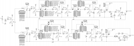
Attached first you'll find a collection of the basic building blocks. Potentiometers are made up of two resistors usually, and if you take the exaple of the relative level control, we have an exemplary resistance of a total of 10k, which is made up of a 5k pot (100 and 4k9) and a fixed 5k resistor. That way the influence of the imperfections of the pot, such as the temperature coefficient, tolerance or noise, is minimized. We will usually never need full attenuation, so we don't need an actual 10k pot. The rest should be self-explanatory.
Next you'll find a sample 24dB/octave LR 3-way crossover with fictional crossover points at 1/(2*pi*10k*60n)~265Hz and 1/(2*pi*10k*4n)~4000Hz. There's a global volume control, a buffered passive RC BSC centered at around 380Hz and buffered level controls for each path. One such channel would draw around 400mA of DC current (per polarity).
The frequency plot looks alright, but the phase plot looks funny.
Thoughts?
Attachments
Mox and Moxlite give all the options one could ever ask for.
The opamp locations could be filled with jFETs.
Each opamp location is for a dual. That could easily be filled with a dual jFET follower of the B1 style.
There were at least three PCB styles, one was for full experimenters level of adjustment.
Others were more stripped down versions after the experimenter had found what slopes and what turnover frequencies and what Q values suited the speaker drivers.

Anytime I ask questions on a forum I also provide help. Read 20 thread titles and you gentlemen have an understanding and experience that's on another level than myself. Keen, yet very new to home audio.
Read this thread, you guys sound like you're very well off. All about the direction you want to take it seems.
FWIW, tried to help
Read this thread, you guys sound like you're very well off. All about the direction you want to take it seems.
FWIW, tried to help
A big !thank you! goes out to the Master Nelson Pass...
We can add a third way, plus Notch filter, plus Delay correction... with some help with opamps or a discrete opamp...
I've not skills to understand everything in your circuit but it seems to me that almost everything has been discussed here is in!
Is it your design or... is it by Nelson Pass?
...waiting for most wise comments than mine...
Last edited:
I've not skills to understand everything in your circuit but it seems to me that almost everything has been discussed here is in!
Is it your design or... is it by Nelson Pass?
...waiting for most wise comments than mine...
I really like the adjustability of this design. I too am curious if this is Nelson's B4 or your simply your own implementation of similar adjustability to the B1 design discussed so far.
I really like the adjustability of this design. I too am curious if this is Nelson's B4 or your simply your own implementation of similar adjustability to the B1 design discussed so far.
Everything starts here: http://www.diyaudio.com/forums/pass-labs/153447-two-b1-crossover.html
plus B5 crossover, last 10 years listening to open baffle plus Pass amplifiers... and based on B4 manuals and Linkwitz site there is nothing else need it! (Elliott diy also)
Alright, here we go again.
Attached first you'll find a collection of the basic building blocks. Potentiometers are made up of two resistors usually, and if you take the exaple of the relative level control, we have an exemplary resistance of a total of 10k, which is made up of a 5k pot (100 and 4k9) and a fixed 5k resistor. That way the influence of the imperfections of the pot, such as the temperature coefficient, tolerance or noise, is minimized. We will usually never need full attenuation, so we don't need an actual 10k pot. The rest should be self-explanatory.
Next you'll find a sample 24dB/octave LR 3-way crossover with fictional crossover points at 1/(2*pi*10k*60n)~265Hz and 1/(2*pi*10k*4n)~4000Hz. There's a global volume control, a buffered passive RC BSC centered at around 380Hz and buffered level controls for each path. One such channel would draw around 400mA of DC current (per polarity).
The frequency plot looks alright, but the phase plot looks funny.
Thoughts?
I'm sure that you have thought of this, but a 6dB followed by two 12 dB XO with options to by-pass ala the B4 could yield 6/12/18/24 XO and make everyone happy. I also really like the switched level control for attenuating either the high or low pass signals as implemented in the B4 as it is true you only need to attenuate one of the two, but may not know apriori which one. Of course, the resistor switching for frequency adjust is pretty neat too.
So the real question is how long before we see a group buy for boards?
That's the thing. I am not settled we are there yet.
One board that has all those items and (three types in a row).
I am not certain Prooptki stuff is tested or if the source goes against any of Papas classified work. But either way, I think easy DB and xrossover frequency switches are a good way to go. If you are uncertain, play with then, and if your hard against them, fine to tune then remove and put in a hard resistor.
This board will need to be prototyped first by me and someone else who builds fast. It's not a simple circuit, but eagle eyes and a well known understanding of the design can avoid problems.
Buffers and Power supply duties will need to use existing Salas boards.
Tea
- Status
- This old topic is closed. If you want to reopen this topic, contact a moderator using the "Report Post" button.
- Home
- Amplifiers
- Pass Labs
- B1 Active Crossover