Peroz, move the driver position closer to 1/3 toward the small end and it'll smooth out considerably. The correct position is not exactly 1/3rd but will get you close.
The thing that seems to make the curve smoother is to increase the density of stuffing.
Moving the driver towards the closed end seems to mostly make it smoother, but also makes the dips that survive, deeper... I guess it's not really an exact science, pleasant sound.
")
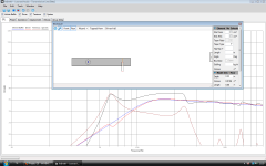
The response exhibits a peaky Fb, common to what happens when the enclosure is tuned too low. The peak at ~140 and 240 are resonant peaks that would not allow use for anything above say 120 or so as it is modeled currently. As is would exhibit bad ringing at these frequencies. Add some dampening to the line. Medium density should work as a start.
Not having modeled this driver before I would say once corrected would be much better.
FYI an expanding mltl is the hardest to get right. Try modeling a negative taper (close the big end and place port on small end) or a straight line and place the driver at 1/3 from the closed end. If the driver is over extended it will show up in the displacement, best check that to ensure Xmax is not exceeded.
If this was corrected would certainly suggest a high pass filter due to loss of comtrol below 50Hz or so.
After having a look at the driver it would be better suited for a sealed box and using it for a midrange. It only has an Xmax of 0.25mm, a low effeciency of 82dB and limited power handling. To hear 50Hz would require a more power than it is capable of handling. Exceeding Xmax creates massive 2nd harmonic distortion.Try finding a driver with a much more substantial throw and a lower Fs. The lower you go the more displacement is required eg for every octave lower, excursion is 4x more.
These are the reasons many like FAST setups. Small driver for everything up high and a sub.
These are the reasons many like FAST setups. Small driver for everything up high and a sub.
Thank you for your input. I bought the drivers because they really are dirt cheap, and a lot of people seem to get decent sound from them in all kind of TLs and horns and so on... It puzzles me, if it is so inappropriate for the needles, why so many people are reporting of good results?
Because good is a subjective word. You will often find in the fullrange forum lots of good but without measurement.
A good driver would be the dirt cheap Vifa TC9FD18-08. Better power handling, flatter response, more Xmax and lower distortion. A far more capable driver for your money.
A good driver would be the dirt cheap Vifa TC9FD18-08. Better power handling, flatter response, more Xmax and lower distortion. A far more capable driver for your money.
Because good is a subjective word. You will often find in the fullrange forum lots of good but without measurement.
A good driver would be the dirt cheap Vifa TC9FD18-08. Better power handling, flatter response, more Xmax and lower distortion. A far more capable driver for your money.
Too bad I can't seem to find this Vifa aywhere near... And it is even cheaper than the Visaton. Must make a note to buy it when I can, thank you for your suggestion.
Now I'm playing on with modeling software, and kind of got lucky with this mltl model, still for the Visaton. Any commentary would be appreciated. To me, it looks promissing. but then again, I never designed my own speaker in my life...
Attachments
HELP - LEONARD AUDIO SOFTWARE
Hi,
I am trying to use Leonard Audio to create an ML-TQWT enclosure for an 8inch full range driver, but after i've put in the driver and amplifier parameters, I'm struggling to get to grips with the enclosure building process. Are there any examples? or other help files other than the one given.
Thanks,
Ryan.
If i can help in any way ... http://surfandsound.wordpress.com/category/sound/
bug?
Hi, want to report a possible program misbehaviour.
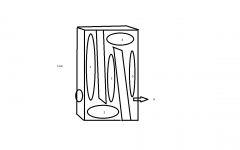
I was trying to model a box for the Beyma 8AG-N, so I create an expanding tube, set boundary -closed-, then "split element", then "create branch", set branch "boundary -open-", and set area and lenght to define it as the vent.
Till this point, everything was OK, I was able to drag the driver, and the vent (ie the split line partition) back and forth, in order to find the best relative position along the enclosure main axis. But after a modification of the enclosure start area, the possibility to drag the vent was gone, It wasn't possible to move it along anymore. Any one else experienced this problem? (see the troubled sim in the attachment)
Hi, want to report a possible program misbehaviour.
I was trying to model a box for the Beyma 8AG-N, so I create an expanding tube, set boundary -closed-, then "split element", then "create branch", set branch "boundary -open-", and set area and lenght to define it as the vent.
Till this point, everything was OK, I was able to drag the driver, and the vent (ie the split line partition) back and forth, in order to find the best relative position along the enclosure main axis. But after a modification of the enclosure start area, the possibility to drag the vent was gone, It wasn't possible to move it along anymore. Any one else experienced this problem? (see the troubled sim in the attachment)
Attachments
Ran your model and the driver position moves. Hard design to deal with as it is with expanding lines. For giggles ran a couple mods, didn't like the results. Driver specs.... Hmmm Beyma doesn't list the specs. Fullrange, 96dB effeciency 35w handling. You have the driver specs as
Bl = 6.662Tm
Sd = 0.022m
Qes = 1.25
Qms = 3.82
Qts =0.942
Cms = 0.000258m/N
Mms = 15.3269g
Lvc = 0.6mH
Re =7.2ohms
Fs = 80Hz
Vas = 18liters
Rms = 2.0168N.s/m
First off the drivers high Q is problematic. I'd suggest a tapered design instead of expanding. Typically you'll want to have the enclosure Vb = Vas. ATM your enclosure is 106liters, driver is 18liters. By extending the low end will result in a mistuned high peak around 50Hz in this case. The result will be boomy and easily overdriven beyond Xmax.
I've attached a new tapered enclosure that should work better and use far less materials.
Hi Greebster,
the design isn't important, just an example to display a problem. The driver moves, always.
What doesn't, is the dotted split line, (ie the vent position), after any modification of the start area, or the end area.
The program is supposed to permit You to move the speaker position, and the vent position , at your discretion, always...
Mosquito, the port cannot be moved unless the section has parallel walls. With a straight TL it moves just fine. PITA I know, but this isn't cad software that can auto create walls.
With these changes and to Qes and Qms to get a Qts 1.42 was guess work. Vas was also halved, which is not good at all. Double or triple the original value would be much better. Fs rose 33Hz to 113 which makes it even harder to get a respectable result. Unless you measured better T/S parameters I would not suggest this driver for TL use. Perhaps OB is best for this one.
robotc, thx for the link. I'd already DL'd the pdf and Beyma neglected to state these limited specs.
Ok, this is probably because English is not my native language, and I failed to make clear my point.
My question is about one program functionality , independently of what driver you like to use.
The same problem will be present if you use a Fostex, a Lowter or whatever.
You can move the split line (and the associated branch) ie the vent, when first created, until you make any change of enclosure dimensions. Then you lost this possibility.
Hi guys, sorry I haven't been around for a while. Busy times!
So, you can always move the driver along the primary branch regardless of what you do to that branch and how many splits it has.
It's not quite the same with moving a split.
If you have a tapered line (lets say 200cm long with Start Area 1000cm² and end area 100cm²). If you split that element then you can drag the split line.
So you should note here that you do NOT have to have parallel walls to be able to move the split line.
If, for example I move the split line to 50cm along the line then I have two 'sections':
- One is 50cm long with start area 1000cm² and end area 775cm².
- The second is 150cm long with start area 775cm² and end area 100cm².
The program allows you to move the split line because the two tapers are the same (i.e. the two pieces can be represented by one piece).
However, if you now change the end area of the second section to 775cm², then you have two pieces with different tapers and you are not able to move the split line anymore.
This is because the program wouldn't know what to do. Which taper should it use? etc.
However, if you fix the sections, by making the end area 100cm² again then you will be able to move the split point again.
I think I could make this work a little better but it would be quite hard to do
Hi there,
after driving through this 'Route 66 Pages', looking how this simulation program evolved from TL simulator to Horn, Vented and Closed box simulator, I wondered if it can be upgraded to Passive Bass Radiator, Aperiodic and Onken type boxes?
Especially Onken type, as at the moment I have some drivers that could be used in this configuration (selfish, I know...). Or at least, if someone can give me a clue how to simulate it with the possibilities of this simulator as it is.
Thanks, Vedran
BTW, GREAT, GREAT work this TL simulator!
Folds
I recently started playing with the Leonard audio software. The ability to store driver TS parameters and easily plug them into a particular box is nice. I am still not sure how to do folds though. Suppose I had a box with a tapering line created by two internal baffles, the first of which starts at the top of the box and the second which starts at the bottom of the box. How do I divide it into areas or "elements"?
Can I do three areas: the area top to bottom in front of the first internal baffle, the area top to bottom between the first and second internal baffle, and the area top to bottom between the second baffle and the back of the cabinet?
Or do I need 5 or six areas: 1. The area from the top to the bottom of the first baffle, 2. the area from the front of the cabinet to the front of the second baffle with a height the distance from the bottom of the first baffle to the floor of the cabinet, 3. the area from the bottom of the first baffle to the top of the second baffle, 4. the area from the back of the first baffle to the back of the cabinet with a height the distance from the top of the cabinet to the top of the second baffle, 5. the area from the top of the second baffle to the bottom of the cabinet, and 6. the 3/4 inch or so area that exits the cabinet?
Also, I am not sure what to do with the ability to move elements to an angle.
Attachments
- Home
- Design & Build
- Software Tools
- Transmission Line Modelling Software