Also, in that Bob Brines paper, he sets s0 to .1*sd. Martin King states that it should never be smaller than sd. He calls it throat area, I believe they're the same thing. Do you know what's more appropriate as a starting point?
Technically, neither is even remotely correct as stated since driver specs, horn flare and frequency factor comes into 'play', but unless you have a clear understanding of the various horn alignment design routines or at least use Hornresp's horn designer, then as the 'BIB' horn and hundreds of successful DIY tapered designs have proven, a default ~0 - 1x Sd is fine.
Haven't done any actual comparison tests between horn design Vs defaults, but in sims the only substantive performance difference between any of these is the amount of stuffing required to smooth them out, so unless getting the absolute max acoustical efficiency BW out of an alignment is the primary goal, then use whatever is easiest, most space efficient to build even if a larger 'throat' is required.
Note that ideally/historically you want a vent area [Av] = ~0.7 -1x Sd, though with the advent of T/S, designing based on a < 0.5 vent mach is sufficient and often results in a bit smaller one.
Note too that a program will calculate this value on whatever peak power and Fb is used, so if Fb is a bit below the lowest high SPL frequency it will be 'told' to reproduce, then you can design a smaller, shorter vent/TQWT terminus based on this lower power value.
GM
Thanks GM. My design with it set to about .2xSD looks fine to me. I really don't see a lot of change in the upper harmonic dip like MK said there would be.
On a different topic- I've set up a new computer and installed the LA software again on the new machine. But now, adjustments made in the enclosure section have no effect on the model's graphs. Does anyone have an answer to this one? Thanks!
On a different topic- I've set up a new computer and installed the LA software again on the new machine. But now, adjustments made in the enclosure section have no effect on the model's graphs. Does anyone have an answer to this one? Thanks!
Actually, it looks like I can update the model to reflect changes in the enclosure window, but only by clicking update in the model page. Changes in the enclosure page are not automatically reflected in model like they were on my old computer.
Make sure you have the wrench button at the top left of the enclosure window on (it has a blue border when on ) to automatically update the model.
Robert
Thank you very much. Now I feel kind of ridiculous, but I read the help file earlier and I don't remember seeing that listed. Not sure why I didn't just click on the damn thing to find out though.
Nice!
Can I suggest that on the driver input page:
- Sd should be in cm^2 by default
- Lv should be in mH by default
All the datasheets I have seem to use these conventions.
Is it possible to choose multiple drivers?
Also when I selected 'expanding' the driver disappeared and I think at one point the enclosure params all cleared too.
Areas and stuffing etc
I find it hard to visualise the lengths and areas in m and m^2. Lame, I know, perhaps the default should be cm.
Also, I find the response extremely ragged unless the stuffing density is pushed way up, beyond 3.
I played with the mathcad models a long way back, and I don't remember that effect then.
Also an observation on the UI: only the main graph window is registered t show an icon, and selecting it doesn't raise the windows for the design.
I think it might be better if the windows were all in the main graph window, perhaps as tabs to a parameter area to the side, so there's a split between a tab set for model inputs and a tab set for graph outputs.
It took plenty of clicking around before I found how to specify a driver (and I didn't read any instructions first, clearly. Who does that?)
Can I suggest that on the driver input page:
- Sd should be in cm^2 by default
- Lv should be in mH by default
I find it hard to visualise the lengths and areas in m and m^2. Lame, I know, perhaps the default should be cm.
The units for the various parameters for the enclosure and driver are easily changed by clicking on the unit to toggle through a selection. Choose the one you want
Also when I selected 'expanding' the driver disappeared and I think at one point the enclosure params all cleared too.
Do you mean selecting 'expanding' using the wizard button? This selects a starting design based on your speaker parameters. It will replace your enclosure design if there is one.
Is it possible to choose multiple drivers?
As far as I know you can only show one driver on the model enclosure but I have designed with two identical drivers by modifying the Ts parameters appropriately depending if they are connected in series or parallel. And then placing the speaker on the model enclosure midway between the two drivers in the actual enclosure
I recommend reading the TL Users Guide available in the Help menu
Robert
I'm late joining this thread however am entering into the design phase of a set of dual woofer TL's myself. Where can I get the tool being discussed here? I'm wanting to model 2 cabinets, the lower using 2 Silver Flute w14 (5.5") and the second cabinet will play a single Fostex Ff85wken. These cabinets will be bi-amped as well..
You're welcome!
FWIW, it's arguably the easiest to learn of the ones that can 'accurately' design TLs. Also, 'newbies' tend to be overwhelmed, over think, these programs, but with the advent of 'slider' controls that give real time updates, it really is very easy/quick to get 'up to speed'.
Another 'stumbling block' is that the response plot looks overly complex since TLs have 1/4 WL [1/2 WL if tapered] resonant modes that in a program like this that doesn't take any damping [acoustical or otherwise] into account can be quite confusing, so normally one adjusts the driver location to minimize how 'bad' they look and not be bothered that it will still look pretty ragged.
Note too that what matters most is only the BW up to ~[2*Fs/Qts'] as the 'hash/ripple' higher up is normally damped down from the internal stuffing.
Qts' = driver Qts + any added series resistance, which usually is an insignificant ~ 1/2 ohm foe wiring unless it's overly long and/or small and/or there's a passive XO and/or coupled to a high output impedance [tube] amp: mh-audio.nl - Home
GM
I'm wanting to put a pair of these into each cabinet. I will build separate cabs for Fostex ff85wken to handle the higher stuff...biamping the set for power.
Do you have any first impressions or advice for a project such as this? Perhaps a known design? Thanks in advance for any help..
Silver flute w14rc25-04
Material : Wool Cone
Cast Frame
25mm VC Ø
Vented Pole Piece
Rubber Surround
F3 of 75Hz in 0.2 ft3 ported enclosure
Re 3.7 Ohms
Sensitivity 90 dB
Power 60 watts
Fs 42.5 Hz
Qms 3.70
Qes 0.31
Qts 0.28
Vas 19.0 Ltrs
Mms 7.95 g
Cms 1767.6 mM/N
Sd 0.0087 M2
BL 5.07 TM
X-max 3.5 mm
Le @ 1kHz 0.52 mH
Frame Ø 142 mm
Cutout Ø 122 mm
Depth 67 mm
Krm 0.913 mW
Kxm 8.302 mH
Erm 0.840
Exm 0.684
Box Rec.: 7 ltrs, 1.5"Ø V x 4.25" L
Hmm, these have horn driver specs, which are also good for being driven by SET amps, so what's your performance goal? Planning to use a high output impedance amp?
I mean if you put them in a ported box driven with a SS amp they will be tuned high above Fs or will have little mid-bass/no bass to speak of if tuned to Fs, so ditto in a TL.
GM
I mean if you put them in a ported box driven with a SS amp they will be tuned high above Fs or will have little mid-bass/no bass to speak of if tuned to Fs, so ditto in a TL.
GM
I have a mix of amps... Sansui 8080db, Rotel rb850, an el84 tuber, a fat man tube... Oh another Sansui 2000A as well....I don't play super loud anymore but do love the clean jazz sound. I have a set of pensils wit mark audio 7.3s and a set of Valiants with Fostex 126en's as well.. I'm wanting some bass out of these for sure, biamping with a pair. Of Fostex ff85's as I mentioned before.... Can I tune them to 50hz at least? I want these bass cabinets to mix and match with my other speakers at times... Does that help create the picture? Btw thx for the chat GM
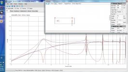
Hello, need some help. I have entered the parameters of the Alpair 10.3 for a ported enclosure, but the spl from 0 to 500hz just shows a mountain shape? nothing beyond 500hz. I have checked to make sure the specs are entered properly, but I must be doing something wrong. I think it must be the way I am entering box dimensions and I am not doing it correctly. This is for ported enclosure. My external box dimensions are H 863.6 mm, W 203.2 mm and D 279.4 mm. Vent is W 76.2mm, L 209.6 mm. I have done this in Bass Box pro and wanted to enter the dimensions into the Leonard Audio program to find the best Driver and Port (port is on front baffle) placing as these can be moved up and down on the baffle, which can't be done in BassBox Pro. Any advice would be great, thanks. 
Hi
I did a quick simulation using your data and came up with the attached frequency plot. The driver is 15cm from the top and I have placed the port about 10cm from the bottom of the box. I assumed a square port because you gave a port width not diameter.
Robert
I did a quick simulation using your data and came up with the attached frequency plot. The driver is 15cm from the top and I have placed the port about 10cm from the bottom of the box. I assumed a square port because you gave a port width not diameter.
Robert
Attachments
- Home
- Design & Build
- Software Tools
- Transmission Line Modelling Software