I am just starting to get some time in front of it. The attributes I've heard so far is that is quite revealing, very fast, lots of clarity and separation. I have heard some very low bass notes that I had not heard before, it has very good and wide frequency range. It does not glare in any area, but being very fast, loud transients can startle. I think it is a tad better than the 49720, but like Bob said, proper implementation is key. Specifically input impedance.
Those CAT6 plenum wires are "supposed" to be x-talk resistant. But I know I could do better with coax shielded type to prevent the x-talk that does still happen. I just like these too much and have a couple hundred feet spool. If you all turn me on to some small signal coax that does not cost too much, I may just switch.
Maybe tonight the pre sees the scope again.
I tend to like RG174.
There are variants of it that are designed for extremely high frequencies in the Gigahertz range that can sometimes be found at reasonable prices at surplus places. Often there will be very low-loss dielectrics and silver-plated stranded copper center conductors and braided silver-plated copper shields. Some of it is quite flexible as well.
Some computer cables used to have multiple shielded twisted pairs in them.
Cheers,
Bob
The CAT5 etc. cables are low crosstalk for low impedance sources and loads. This stuff is all high impedance so the capacitance it the dominant crosstalk mechanism, so shielding is your option. HDMI has 4-6 shielded twisted pairs of cables with low loss insulators. It can be a great source for raw material for wiring up stuff like this.
The best cable for HiFi i found is this :Aircom Plus
Unfortunately it is of big diameter and rather stiff.
The Aircell is nearly as good.
Unfortunately it is of big diameter and rather stiff.
The Aircell is nearly as good.
I use metal oxide too in low values where noise is not such an issue.
For example in RC filters in the PSU.
They are usually availlable in higher wattage then metal films.
I do not use them in the direct signal path.
I am afraid of the cranularity of the material.
That could be the cause for the higher excess noise.
As emitter resistors they are fine though, i agree.
For example in RC filters in the PSU.
They are usually availlable in higher wattage then metal films.
I do not use them in the direct signal path.
I am afraid of the cranularity of the material.
That could be the cause for the higher excess noise.
As emitter resistors they are fine though, i agree.
Cool, thanks for the cable recommendations. I will look into them all.
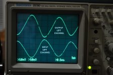
Here are the scope readings, you notice that the saw-tooth wave obtained early on is gone and the output resembles the input.
Oscilloscope Channel 1, bottom half of the screen = signal going into the preamplifier.
Oscilloscope Channel 2, top half of the screen = the output at RCA jack via a short splice of interconnect.
Looks OK no?
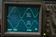
Attachments
Last edited:
Rolling off the frequency response using a cap across the feedback resistor depends on the opamps ability to cleanly operate well above the frequency you want the rolloff at. But the feedback itself is rolling off as you go up in frequency, so by the time you get up to several hundred kHZ, because the feedback has become small, the opamp may not be very distortion free, so it acts like an AM radio detector and generates sum and difference frequencies based on whatever Rf energy is coming in. The feedback necessarily rolls off (even without the cap added) because you need a "dominant pole" well ahead of any other rollofff poles in order to have good phase margin. A dominant pole appears to be designed into all opamps. Look at the open loop F response graph.
So a much better way to dump Rf energy coming in is with a passive Rf filter ahead of the opamp circuit, which is just an R in series and a cap to ground. A true nerd might also put ferrite beads on the incoming wire so then it's an inductor in series and a cap to ground. A 2 pole filter instead of one pole. I don't bother with the beads (maybe I should).
To design this filter you need to have some idea what the source impedance will be. If your source takes a signal from the plate of a tube, you can be way off on this, but virtually all other sources I know of will have an output impedance of less than 1kohm, so I design for that. Since series resistors can add hiss noise I prefer to keep the series resistor small. I usually go with 1k, which adds to the 1K source impedance from the point of view of the cap to ground after the R. So then you just calculate a cap based on 2kohms. Whatever input impedance to ground resistance the opamp circuit will have will create a "zero", which cancels the rolloff, so you want that to be as high as is practical. For a one pole RC passive filter the math is:
C = 1/ (2 times pie times F times R as seen by the cap)
Example: C = 1/ (6.283 x 100kHZ x 2kohms) = 796pF
So then you choose the nearest standard value which in this case is either 820pF (rare but I think they exist) or 1nF (very common).
If you choose 1nF, the actual -3dB point will be :
F = 1/ (2 pie x 1nF x 2Kohm) = 80kHZ
If the R to ground off the + input of the opamp (which this feeds) is 50Kohm or higher, this filter will be pretty effective. It would be more effective if this 50K was 1Mohm, but then you've got a 1mohm R making hiss noise. I usually use 50K there and believe it to be a good tradeoff.
This Rf filter is for signals coming into the chassis. I don't put one of these on each stage within a given chassis.
A series R at the final output of a preamp circuit, for example (usually 100 - 200 ohms) will make the opamp more stable (very important), and also form an RLC filter with the interconnect cable that goes to the poweramps, so it's good to be aware of how much capacitance that interconnect cable will have if it's very long. It will form another passive Rf filter itself.
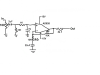
Bob, while you're on the subject of Rf filters, what if you have a 10K volume pot and a 1K resistor in series with the + input of the op amp like in the circuit below that I've been working on?
What value of R would you use to calculate C?
Thanks...
Attachments
In such cases with a pot , the equivalent pot resistance also comes into play and that depends on it's position ! If you had it connected to the output of a preamp with very low Zout, then 1K would be the value used.
But with a pot as shown at the worst position ( 50 % ) it should be 5k//5K+ 1k or 3.5 K.
With the 9K at the input it complicates it a bit more. You'll need to find the highest value you get with pot rotation and 9 K in parallel. I'm guessing it may be around 1.96K. So your R value would be 1.96K+ 1K = 2.96K.
Last edited:
The LME49713 will roll of at high frequencies but way beyond what you might think of a radio. It is pretty flat to about 50 MHz: http://www.ti.com/lit/ds/symlink/lme49713.pdf Fig 22. Do not add a cap across the feedback (as mentioned earlier). I would add a ferrite bead in series and a 100 pF cap in shunt before the Buffer opamp. Do you really have a 35K resistor in series with the + input of the opamp? That will be a serious rolloff and noise catcher. I would use 100 Ohms there.
Maybe we need an updated schematic to understand what you have.
Maybe we need an updated schematic to understand what you have.
In such cases with a pot , the equivalent pot resistance also comes into play and that depends on it's position ! If you had it connected to the output of a preamp with very low Zout, then 1K would be the value used.
But with a pot as shown at the worst position ( 50 % ) it should be 5k//5K+ 1k or 3.5 K.
With the 9K at the input it complicates it a bit more. You'll need to find the highest value you get with pot rotation and 9 K in parallel. I'm guessing it may be around 1.96K. So your R value would be 1.96K+ 1K = 2.96K.
I wasn't sure.
Thank you for your reply!
Aim for 100kHz to 300kHz as your RF filter.
But I really do recommend using a buffer on the output of your vol pot.
vol pot cannot drive cable capacitance.
If the cable is 100mm long then you only have to be concerned with the variable source impedance being presented to your stage.
If the cable is >1m long then add a buffer with an output impedance <200ohms. ~10ohms to 50ohms is better if the buffer will remain stable with all loading options.
The 49713 pre had been working great. It is still the best one around here. But, as of late it seems to be oscillating.
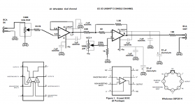
It starts as a small hiss building up louder to a snap/pop, then quiet, then starts the process all over again. I drew up the schematic.
Anyone venture me any ideas on this oscillation? Offset is steady near 0 VDC (1.3mV) on both channels. And both channels exhibit this and the metal can 49713 feel warm to the touch. How do I control BIAS in the op amp?
Otherwise it is a fantastic performer.
Attachments
The 49713 pre had been working great. It is still the best one around here. But, as of late it seems to be oscillating.
It starts as a small hiss building up louder to a snap/pop, then quiet, then starts the process all over again. I drew up the schematic.
Anyone venture me any ideas on this oscillation? Offset is steady near 0 VDC (1.3mV) on both channels. And both channels exhibit this and the metal can 49713 feel warm to the touch. How do I control BIAS in the op amp?
Otherwise it is a fantastic performer.
Hi Whaleman
Start with a 100pf ceramic across the 1.2k ohm feedback resistor. This should help to tame it
")
Cheers Anthony
I'd be rather wary of any capacitance across the f/b resistor as the opamp here is of the CFB kind.
Good point! I did not take enough notice of the model number.
I was assuming voltage feedback.
Then an small increase in the feedback resistance could help and scaling it with the 330 ohm to preserve the overall gain.
or the 82 ohm input resistor might be worth a look as well.
Cheers Anthony
Last edited:
A 1K is good for most source impedances (usually 100 - 200 ohms with opamp circuits), unless they are above 1K for any reason. Taking an output from the plate of a tube would be a problem. I wouldn't put the cap right at the input of an opamp. Some opamps don't like that. Could cause oscillations. I'd jack up the output resistor to at least 100ohms. I'd actually put the Rf filter before the pot. From the input: a DC blocker, then a 1k R, then a cap (1nF will give you a 3dB down point of 160kHZ) to gnd, then the pot (I'd use 50K - 1M depending on what the source will be happy with - lower would be less noisy, but could cut bass if the source has a whimpy DC blocking cap), then a 1k R from the wiper to the opamp + input. Some opamps don't want their input tied directly to gnd either, which would happen when the pot is turned all the way down. Not likely a problem, but why risk it.Bob, while you're on the subject of Rf filters, what if you have a 10K volume pot and a 1K resistor in series with the + input of the op amp like in the circuit below that I've been working on?
What value of R would you use to calculate C?
Thanks...
Good point! I did not take enough notice of the model number.
I was assuming voltage feedback.
Then an small increase in the feedback resistance could help and scaling it with the 330 ohm to preserve the overall gain.
or the 82 ohm input resistor might be worth a look as well.
Cheers Anthony
I decreased the gain by replacing the 1.2K feedback resistors with 912 ohms, no difference, same snap, pop, repeat.
There is no need for the resistor between pot and opa2604. The opa2604 has to drive a load which is much too low. I don't know about driving a current opamp inverted, but without good reason to do so I would just follow the app notes.
That is what I thought, but it was needed. Don't remember at this point what it did without it.
Any other ventures?
I decreased the gain by replacing the 1.2K feedback resistors with 912 ohms, no difference, same snap, pop, repeat.
Decreasing the gain if anything is only going to make things worse.
With current feedback opamps its the internal capacitance and the feedback impedance which sets its stability so to speak. case in point is your use of the 82 ohm input resistor, this might actual need to be increased and the same goes for the feedback resistor values I would try something like 3k3 ohms and 820 ohms, instead of 1k2 and 330 ohms.
This is assuming of cause that the issue actually is with this part of the circuit.
Cheers Anthony
Agreed on both points. This implementation tries very hard to squeeze the worst-possible performance out of the '2604... huge impedance imbalance, significant output loading, presumably "normal" (like +/- 15 V) supplies. Ideally I'd want to modify the circuit so it can accept a bipolar, but for a minimally invasive solution, I'd probably reduce said resistor to ~220 ohms (and ideally the pot to 20-50k) and drop in an OPA2132 instead.There is no need for the resistor between pot and opa2604. The opa2604 has to drive a load which is much too low.
As for the intermittent oscillation, sounds like a bad solder joint somewhere, or a faulty part.
EDIT: If it needed a series resistor that high, I'd suggest adding like 220-300 pF to ground after the resistor. And as mentioned, bandwidth reduction on the '49713 would probably be a good idea.
Last edited:
I tried all these suggestions. There was a good deal of hiss, enough for the pre to be unusable. I remember now that the 32.5K input resistor was necessary to eliminate the hiss, I tried 220 and 1.2K ohms at the input of the 2604 buffer and tried different combinations of input/FB resistors at 49713. No workie...
- Status
- This old topic is closed. If you want to reopen this topic, contact a moderator using the "Report Post" button.
- Home
- Amplifiers
- Solid State
- National opamp inflation