I ask because Mike Lenehan has finally found a non-ladder DAC that in his view is better (their own Ghistler/PDX Konverter [with a "K"] with 1704U) in the new PS Audio Direct-Stream DAC. I never thought that I would hear him say that. It outputs at 5.6xMHz and uses transformers. That is double-DSD or same as DSD128, is the Sabre same as DSD64? The PS DAC definitely uses s-d modulation.
Ted uses an FPGA implementation to get an intermediate format which is similar to DSD at 10x rate, and this is then down-converted to DSD 2x for output.
At the output stage, he did some clever use of the actual output transformer for the filtering so as to have less negative impact on the sound.
Very clever bloke! Look for his technical presentation on Youtube where he gives a lot of information on his design decisions and the implementation.
By the way, glad to see this thread going strong with the 'Rasmussen effect' and now, Coris's experimentations with power supplies.
I still remember the first, but can anyone fill me in as to what Coris is up to?
Thanks a lot (I am reading the thread backwards
 )
)Ted uses an FPGA implementation to get an intermediate format which is similar to DSD at 10x rate, and this is then down-converted to DSD 2x for output.
At the output stage, he did some clever use of the actual output transformer for the filtering so as to have less negative impact on the sound.
Very clever bloke! Look for his technical presentation on Youtube where he gives a lot of information on his design decisions and the implementation.
Your description is quite accurate, but may I add that down-converting to DSD x 2 (or DSD128) Ted Smith is using a delta-sigma modulator, indeed says so in one of his videos, that must be working at 5.6MHz.
Note two that DSD x 10 (28.2MHz) also happens to be an integer value multiplier for both 44.1KHz and 48KHz, which is very clever indeed. Indeed 44.1KHz x 640 = 28.224MHz and 48KHz x 588 also = 28.224MHz. So no fractions are involved with all inputs and they can be integer multiplied to DSD640 (DSD x 10).
Yes, very clever indeed.
But... there is no multi-element low bits after the d-s stage which is normally used (and this is an area that I have no expertise). This means, from what I gather, and the Atkinson measurements indicate that based on noise, the resolution is only 17 bit. But that I believe should not be used as a final assessment of the approach, where the standard rule/convention is that the noise floor determines the resolution in equal bits. If that were so, that would be a negative strike against it - but I am not sure that it should looked at this way, so Ted is simply doing it his way and good on him.
Terry Demol, known to many here, has told me that eventually all this will be software based and not FPGA - so FPGA may well prove to be just a step down that way. What JRiver etc is doing seems to be pointing that way. We shall see.
I have heard Ted's DAC, a friend of mine and partner of Michael Lenehan, is associated the Magenta (link to Magenta Audio) - so indirectly via those guys, I am connected on the periphery - and I spent three days at Southport Hi-Fi listening to both the Direct Stream DAC and my own JLTi Oppo 105 (L3.11) and the latter was competitive, to the extent that Southport Hi-Fi, with a direct connection with Magenta, will be handing the upgraded Oppo as well.
BTW, I also use transformers with the less expensive Oppo 93 and 103 (and other players with 'voltage' DACs) and using the tx as part of the post-DAC filtering, which has now been proved to be far more important than ever thought before.
By the way, glad to see this thread going strong with the 'Rasmussen effect'...
That is what proves the post-DAC filtering to be critical and the fact you have to be brave to implement it.
For those who worries about the filter, then here is the solution to that as well:
When the "Rasmussen Effect" is implemented, and when using USB DACs with Media Centers like JRiver, then JRiver operating at 64 bits and also has an inbuilt Parametric Equalizer, then flatness at 20KHz is easily restored, by picking three values, 40.000Hz, +4dB and Q = 0.6.
Now the playback will again be flat at 20KHz and nobody needs to get their nose out of joint (I always found that a funny phrase).
Re Coris power supplies, it is interesting that we both have worked this out almost independently. But the reason why this works is very much the same reason why Ted Smith puts a 1 Hertz filter on his power supply at the delta-sigma modulator, because the on/off states, then the 'on' state, any noise or any aberration on the rail (likely +3.3V) will end up as jitter and very audible indeed. Ted is using a filter, Coris and I are storing massive amount of energy (effectively massed electrons acting as an electronic flywheel) that makes the rail very hard to move or modulate, as well as stacked ceramic film caps (these are made by Murata) as by-passes (I use double 47uF) and these are very effective methods.
In many ways, a LOT of things have been coming together and we believe that we are indeed improving digital playback in significant ways, so whether Ted or Coris and indeed myself, we ALL want the same thing.
It has been a very interesting year !!!
Now, if next year, Ted Smith might try sampling the "Rasmussen Effect" and see if that does anything for his Direct Stream DAC? That could be interesting.
Cheers, Joe
Last edited:
I am very interested in upgrading the clocks on my Oppo BDP-95 and was going to pursue this as a DIY modder until someone pointed out that this type of mod should be left to the experienced, and not to the DIY hobbyist armed with a soldering iron and upgraded many analogue components such as myself.
My goal is to have the audio section enhanced as much as possible on both the two and all-channel as-much-as-possible. So the question is - which DAC upgrade should I go with? There are three to choose from - which are all from fully capable experienced people.
I seen the Jae Hong Lee TCXO Clock. It looks very simple where I can perform the DIY mod myself, but I am not certain if his solution is a better performer than Coris, Joe R., or Ric from EVS.
Ric uses the modified Dexas which sounds tempting, and Joe R. uses Tera-Firma and SAW. However, Coris uses something different - sorry not certain what he uses or if it is also Dexa - but he also uses other interesting techniques that are very intriguing. Coris has the best option of all where I would only have to ship a board instead of the whole unit.
I put in a purchase for an LPM-SE Power Supply to replace the SMPS power supply from Jae Hong Lee. It shipped today.
I would be willing to ship my board to Coris, Joe R., or Ric from EVS. Coris shows the most potential and work from what I seen here in this message board based on pics, although Joe R. and Ric both have much experience in the field and has majorly contributed in this forum - as Coris has.
Sorry if this has been answered already, however I would prefer to go straight for the answer without having to jump through the 117 pages that is in this discussion.
So what is the verdict based on everyones experience?
However, Coris uses something different...
He is the second person after me to use SAWs - I think he uses 108MHz and divides down to 27MHz. I will let him confirm that.
Cheers, Joe
.
This is confirmed:
SAW oscillator (second user, after Joe...), as follow:
216Mhz, divided to 108Mhz for DAC, and the same 216Mhz divided to 27Mhz for processor. Then two options: for BDP105, another 20Mhz oscillator for HDMI chip. For BDP105D, no extra oscillator, as the video stage it use the same 27Mhz clock frequency as for processor. So, the same clock frequency is shared for these circuits.
Dividing and using a unified clock signal/frequency it have some advantages, but the main advantage of my solution is the directly battery power used for these clock generators. And even more, the damping mechanical system for the whole board.
The overall result, is a quite good clock signal for the targeted device...
My solution it have another option too. The battery power system/board it can host all the three different oscillators in a independent setup (no divider). SAW 108Mhz oscillator for DAC, 27Mhz oscillator for processor, and 20Mhz oscillator for HDMI (BDP105), in the same configuration as Oppo have chosen, but powering all these oscillators from battery, and using the same mechanical approach..
By the way, only the board (4 layer design, and equipped only with the battery charger circuit, and the control relays, it can be used for up to 4 different footprints oscillators (Crystek or another SMD types), for a very customized configuration, on whatsoever device. The board also provide access to the all 4 oscillators Enable pins.
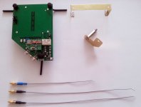
The available kit it looks like in the picture here, only the board circuits design are revised and upgraded.
SAW oscillator (second user, after Joe...
), as follow: 216Mhz, divided to 108Mhz for DAC, and the same 216Mhz divided to 27Mhz for processor. Then two options: for BDP105, another 20Mhz oscillator for HDMI chip. For BDP105D, no extra oscillator, as the video stage it use the same 27Mhz clock frequency as for processor. So, the same clock frequency is shared for these circuits.
Dividing and using a unified clock signal/frequency it have some advantages, but the main advantage of my solution is the directly battery power used for these clock generators. And even more, the damping mechanical system for the whole board.
The overall result, is a quite good clock signal for the targeted device...
My solution it have another option too. The battery power system/board it can host all the three different oscillators in a independent setup (no divider). SAW 108Mhz oscillator for DAC, 27Mhz oscillator for processor, and 20Mhz oscillator for HDMI (BDP105), in the same configuration as Oppo have chosen, but powering all these oscillators from battery, and using the same mechanical approach..
By the way, only the board (4 layer design, and equipped only with the battery charger circuit, and the control relays, it can be used for up to 4 different footprints oscillators (Crystek or another SMD types), for a very customized configuration, on whatsoever device. The board also provide access to the all 4 oscillators Enable pins.
The available kit it looks like in the picture here, only the board circuits design are revised and upgraded.
Attachments
Last edited:
Re Coris power supplies, it is interesting that we both have worked this out almost independently.
Actually completely independent, as we never had any contact or discussed previously on this subject... But large capacities decoupling was quite often a theme on the posts here...
So far, I had not even the opportunity to see or read about some of the Joe`s findings in this field... Also as I know, was RayCtech who did experiments on this, and who confirmed many of my independent findings, about advantages when using large capacities for decoupling the ES9018 (AVCC)...
However this subject is quite interesting, and are some more interesting things I found out, or I`m going to find out about...
Last edited:
Actually completely independent...
So it would seem. Have you put one on the SAW clock yet?
Well, I`m not using such PSU or caps on SAWs... As I use the battery on it, I found not just necessary to try the large caps yet. But it should work fine, of course.
At least I prefer battery for oscillators (for some reasons...). F. ex. the charging delay it may be a serious issue for clock oscillators...
At least I prefer battery for oscillators (for some reasons...). F. ex. the charging delay it may be a serious issue for clock oscillators...
Last edited:
Not sure adding 'must be working at 5.6MHz' adds anything to the description, since DSD 2x is by definition 5.6MHz.
As for FPGA, it is already 'software' in that hardware configuration can be coded in text. In fact, it's very versatile since one can change the hardware implementation just by describing it in text! Extremely powerful for upgrading. Will implementations go to software (this implies a normal CPU/DSP-based implementation rather than FPGA)? Maybe, because of the ubiquity of the computer but FPGAs are a different beast altogether. Want to change the implementation of DACs inside it? Easy: just write a different hardware description of it - no need to actually change hardware components.
Looking forward to try the Rasmussen effect on my DAC one day.
Not sure I can try whatever Coris is doing as it seems more complicated for hobbyists! But it reminds me of what John Swenson mentioned about power supplies and noise flowing back to the mains, and hence the need for snubber circuits in some amps. I still plan to add one to my SET tube amp, but need to troubleshoot one channel.
Cheers.
Your description is quite accurate, but may I add that down-converting to DSD x 2 (or DSD128) Ted Smith is using a delta-sigma modulator, indeed says so in one of his videos, that must be working at 5.6MHz.
Terry Demol, known to many here, has told me that eventually all this will be software based and not FPGA - so FPGA may well prove to be just a step down that way.
Re Coris power supplies, it is interesting that we both have worked this out almost independently. But the reason why this works is very much the same reason why Ted Smith puts a 1 Hertz filter on his power supply at the delta-sigma modulator, because the on/off states, then the 'on' state, any noise or any aberration on the rail (likely +3.3V) will end up as jitter and very audible indeed. Ted is using a filter, Coris and I are storing massive amount of energy (effectively massed electrons acting as an electronic flywheel) that makes the rail very hard to move or modulate, as well as stacked ceramic film caps (these are made by Murata) as by-passes (I use double 47uF) and these are very effective methods.
Well, I`m not using such PSU or caps on SAWs... As I use the battery on it...
Try it anyway. I have seen spectral noise measurements on batteries some way back and they have increasing noise with descending frequency - so do try it and let me know what you think - been doing it for years. Except I use it within a servo loop that fixes the 3.3V - but in a non-servo, just fit it across or near the power supply terminals of the SAWs. Make sure you have a power supply that can handle it by being current limited rather than overheating, in case the cap is in a depleted state.
Cheers, Joe
Last edited:
OK. I will note this in my experiments plans...
In the mean time I have to see how to handle the huge delay of time these caps introduce in a circuit. Especially when is about a power start up sequence. It may be possible to design/build a power management in this respect, but it may be a question here about the economical reasons in all this... If another solutions may be more simple and as same efficient...
BTW, the batteries were improved in the last time... At least it is not exactly the same approach when using it to power this SAW oscillator, as when to use it for some sort of audio circuits...
BTW again, there is not a must at all, when about a precise and fix value of 3,3v for oscillators (rated for this V+). All these devices it have included inside its own and very efficient power management, which it keep all the specified/guaranteed parameters in the specified levels. The single role of a regulator when to power a such oscillator device, is to lower the noise level induced on its power rail.
Well, my conclusion, after quite extended experiments on this...
In the mean time I have to see how to handle the huge delay of time these caps introduce in a circuit. Especially when is about a power start up sequence. It may be possible to design/build a power management in this respect, but it may be a question here about the economical reasons in all this... If another solutions may be more simple and as same efficient...
BTW, the batteries were improved in the last time...
At least it is not exactly the same approach when using it to power this SAW oscillator, as when to use it for some sort of audio circuits...BTW again, there is not a must at all, when about a precise and fix value of 3,3v for oscillators (rated for this V+). All these devices it have included inside its own and very efficient power management, which it keep all the specified/guaranteed parameters in the specified levels. The single role of a regulator when to power a such oscillator device, is to lower the noise level induced on its power rail.
Well, my conclusion, after quite extended experiments on this...
Hi Joe,
Wow what can I say - I was already very happy with my new PCM1794...
Clay
Have you yet tried my suggestion on the +3.3V to the oscillator?
Cheers, Joe
Member
Joined 2009
Paid Member
This thread focuses on the Oppo Sabre DAC - but it seems to me that this 'big F power supply' could be of benefit to any DAC ?
Yes, true. Of course... Well, DAC based on ES9018. Not tested yet with other chips...
not sure if the on board regs would handel 0.33 F on their out - what do you think?
Hi Clay
Indeed, this is the question that arose from the beginning when starting to use the large F caps.
Early on I remember setting up a lab power supply to +3.3V and feeding a new and depleted 1F cap (checked there was zero volt across its terminals), then set it up to charge the cap via small value resistor and put a analogue scope across the resistor before making the connection. Looking at the deflection on the scope and knowing the value of the resistor, I was able to deduce that surge current. I think you will find that the 0.33F should likely be under 100mA. Also, the onboard regulator, maybe if you can see a number on it and look up the datasheet, see if it has inbuilt current limiter, I would think most have, even humble LM317 and LM337 do. That should make it near foolproof if it was short circuit proof.
These caps have very high dialectic absorption, so they don't present an instant short the way many other caps would. At DC turn-on they are basically a bit slow as my experiments indicate. I don't think you will have any problem, in my opinion, but up to you to chance it.
Cheers, Joe
.
Member
Joined 2009
Paid Member
Yes, true. Of course... Well, DAC based on ES9018. Not tested yet with other chips...
Do you think it would apply to the ES9023 ?
Hi Joe,
you are right as usual - I monitored the charge current on a totally discharged cap & it was extremely low, no big in rush current at all. Weird thing about it is I measured my .3F cap with a LCR (Agilent) & it reads about 150 uf! ESR about 30 ohms.
Even tried another LCR meter - same result - LCR's do not read that high but should display overload. What do you think is going on. supercaps seem OK as they are holding charged voltage no problem
Hi Joe,
you are right as usual - I monitored the charge current on a totally discharged cap & it was extremely low, no big in rush current at all. Weird thing about it is I measured my .3F cap with a LCR (Agilent) & it reads about 150 uf! ESR about 30 ohms.
Even tried another LCR meter - same result - LCR's do not read that high but should display overload. What do you think is going on. supercaps seem OK as they are holding charged voltage no problem
Hi Clay
I don't think they are caps in the usual sense of the word - they also take a very long time to fully form, almost a week in my experience. Although they work from the word go, they get better with time. Maybe you will detect that too from continued listening.
The nature of DA, dielectric absorption, where electrons get deeply embedded and then wants to stay there, then release slowly - try deplete the cap with a resistor for a little while, then measure the voltage before removing resistor and the voltage rises under no load - that's pure DA and there is lots of it. This is OK for battery backup where current is very low and DA is not a problem over time.
I have a theory, but it is a little controversial, that Allan Variance (there is a wiki page for it) is a factor when it comes to digital playback and that the worst jitter is below one Hertz. Rate of change below one Hertz can create jitter? Hard to figure, right? Even Ted Smith only filters his supply above one Hertz (and I am pretty sure it is passive which means it can't be ultra-low impedance) in the 'Direct Stream' DAC.
Whatever, it works, right?
Cheers, Joe
PS: Have you seen this graph?

A very rare measurement of "Uncorrelated noise-like jitter" by Paul Miller. The windowing masks just how low frequency, but it does not mask the huge increase in amplitude with descending frequency. Audible? Paul Miller said it was very obvious.
BTW, the piece of equipment used to measure the above was/is worth over 100 thousand Pounds.
Last edited:
- Home
- Source & Line
- Digital Source
- Oppo's BDP105 - discussions, upgrading, mods...